
Reference Instruction Manual


LPF, 1
st
order
d/dt limiter
PF[13]
PF[7,8,14]
2
Effective
current
demand
Σ
I
q
Σ
I
d
-
-
KP[1],KI[1]
XA[6]
Q - Current
controller
Σ
Speed
correction
KP[1],KI[1]
PF[9]
Q - Current
controller
Σ
Speed
correction
0
Output
Trans-
formation
and
saturation
V
q
V
d
Field angle WS[20]
Input
Trans-
formation
Ia
Ib
Ic
Phase
currents
Va
Vb
Vc
LPF, 1
st
order
PF[12]
DC voltage
3-phase
motors
only
Σ
Cogging correction
lookup table
PN[2]
Current cmd prefilter
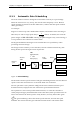
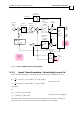
Figure 20: Block diagram of the current controller
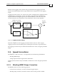
9.1.1 Input Transformation: Calculating Iq and Id
When the motor winding is sinusoidal, the Iq and the Id are calculated as follows:
()
()
2
cos( cos( cos(
3
2
sin( sin(
) 120 ) 240 )
) 120 ) 2si 40 )n(
3
qa c
da c
oo
b
oo
b
II
III
II
I
θθ θ
θθ θ
++++
+=+++
=
(Three phase case,
CA[28]=0)
Or
cos( cos()90)
)sin( sin( 90 )
o
b
o
qa
da b
II
I
I
II
θθ
θθ
+
++=
+=
(Two phase case, CA[28]=0)
This means that when Iq=1, Id=0 the current through each of the motor windings is
sinusoidal, and its peak value is 1 Amp, and its RMS value is 0.707Amp.
SimplIQ for Steppers Application Note The Current Controller
MAN-STECR (Ver. 1.1)
99