
Reference Instruction Manual


Command Description
CA[18]
F
eedback bits (“counts”) per revolution, after resolution is multiplied
b
y 4, in the range [6…530,000,000].
- For Analog Encoders, the resolution for commutation is
always taken as x2
16
, regardless of CA[31].
- For Analog Hall sensors always use CA[18]=65536
- For systems with Halls only, CA[18] is calculated as
CA[19] * 6
CA[19]
T
he number of feedback counts per electrical revolution is
CA[18]/CA[19].
F
or brushless motors, this is the number of pole pairs.
F
or steppers, this is one quarter of the steps count.
CA[21]
P
osition sensor present:
0: No high-resolution commutation sensor. Commutation will be based
on digital Hall sensors only.
1: Main position sensor will be used for commutation.
For rotary motors, each mechanical shaft rotation involves an integer number of encoder
counts, per an integer number of electrical cycles. This means that the commutation can
be kept accurate using:
WS[21] = mod (encoder, CA[18])
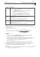
And the transformation angle is
(
)
[18]
[21],
[19]
[20] 360
[18]
[19]
o
CA
rem WS
CA
WS
CA
CA
=×
Examples:
- For rotary Quadrature Incremental Encoders with 1000 lines, CA[18] is 4000.
If the motor is linear, CA[18] reflects the electrical cycle.
- For linear encoder with 1000 lines/m (4000 counts/m) with the distance between
pole sets is 0.1 m, set CA[18] is 400, CA[19]=1. In this example, CA[18] could be
set as any multiple of 400, such as CA[18]=800,CA[19]=2, or
CA[18]=1200,CA[19]=3.
- For Analog encoders,
SimplIQ uses the full resolution for commutation. This
means 2
16
counts per cycle (line), regardless of the interpolation setting of CA[31].
For example, a rotary motor with 8000-line analog encoder and 3 pole pairs
should set CA[18]= 8000x2
16
= 524288000 and CA[19]=3
Note: For good commutation, the number of feedback counts per electrical rotation
(CA[18]/CA[19]) should be at least 36.
SimplIQ for Steppers Application Note Commutation and Pole Identification
MAN-STECR (Ver. 1.1)
27