
Reference Instruction Manual

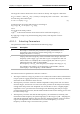

Hall A
Hall B
Hall C
Electrical Rotor
Position (Degrees)
Transformation angle
for best torque
(Degrees)
0 1 0 90 – 150 210
0 1 1 150 – 210 270
0 0 1 210 – 270 330
1 0 1 270 – 330 30
1 1 1 Illegal
Table 4-1: Hall Sensor Arrangements (1)
There are many other Hall sensors arrangements; they differ in sensors polarity, and
offset.
SimplIQ drives are very flexible in accepting Hall sensors; they may be connected with
every order, polarity and offset.
The following parameters define Hall sensors arrangement:
Command Description
CA[1] Digital Hall sensor A polarity (1 for active high, 0 for active low).
CA[2] Digital Hall sensor B polarity (1 for active high, 0 for active low).
CA[3] Digital Hall sensor C polarity (1 for active high, 0 for active low).
CA[4] Actual Hall sensor connector to Hall A connector pin:
1 for A, 2 for B and 3 for C.
CA[5] Actual Hall sensor connector to Hall B connector pin:
1 for A, 2 for B and 3 for C.
CA[6] Actual Hall sensor connector to Hall C connector pin:
1 for A, 2 for B and 3 for C.
CA[7] Offset of digital Hall sensors. The Hall sensor transition electrical angles
are
[30,90,150,210,270,330] deg + CA[7]x360/1024
The units are 1024/electrical revolution.
CA[20] Digital Hall sensors present:
0: No digital Hall sensors connected
1: for Digital Hall sensors connected
Table 4-2: CA Vector - Digital Hall Sensor Arrangement Parameters
SimplIQ for Steppers Application Note Commutation and Pole Identification
MAN-STECR (Ver. 1.1)
25