SimplIQ Command Reference Manual Ver. 4.
Important Notice This guide is delivered subject to the following conditions and restrictions: This guide contains proprietary information belonging to Elmo Motion Control Ltd. Such information is supplied solely for the purpose of assisting users of SimplIQ servo drives. The text and graphics included in this manual are for the purpose of illustration and reference only. The specifications on which they are based are subject to change without notice.
SimplIQ Command Reference Manual MAN-SIMCR (Ver. 4.5) Contents Chapter 1: Introduction ............................................................................................................... 1-1 1.1 Command Specification ................................................................................................ 1-1 1.2 Scope ............................................................................................................................... 1-2 Chapter 2: Functional Listing .........
SimplIQ Command Reference Manual Contents MAN-SIMCR (Ver. 4.5) HL[N] - Over-speed Limit and Position Range Limit ........................................................ 3-56 HM[N] - Homing, Capture and Flag.................................................................................... 3-57 HP - Halt Program Execution ............................................................................................... 3-60 HX - Hexadecimal Mode .............................................................
SimplIQ Command Reference Manual Contents MAN-SIMCR (Ver. 4.5) SD - Stop Deceleration ......................................................................................................... 3-131 SF - Smooth Factor ............................................................................................................... 3-132 SN - Serial Number .............................................................................................................. 3-133 SP - Speed for PTP Mode...............
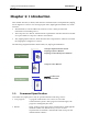
SimplIQ Command Reference Manual Introduction MAN-SIMCR (Ver. 4.5) Chapter 1: Introduction This manual describes, in detail, each software command used to manipulate the SimplIQ line of digital servo drives.
SimplIQ Command Reference Manual Introduction MAN-SIMCR (Ver. 4.5) CANopen Serial, multi-drop, medium speed and medium-range communication. This type of communication requires specialpurpose host hardware and software. This manual describes the SimplIQ commands that can be specified from each of these sources. Most of the commands are equally available for all three sources. Certain commands, however, are limited in scope according to type of program or communication.
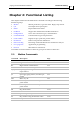
SimplIQ Command Reference Manual Functional Listing MAN-SIMCR (Ver. 4.5) Chapter 2: Functional Listing This chapter summarizes the Metronome commands according to the following functional groups: Motion Motion parameters, type and status. Begin/stop motion. I/O Set outputs and report inputs. Status Report Metronome status. Feedback Support the multi-featured feedback interfaces. Configuration Servo drive and motor types, and limitations.
SimplIQ Command Reference Manual Functional Listing MAN-SIMCR (Ver. 4.5) 2.2 I/O Commands Command Description Page AN[N] Read analog inputs 3-8 IB[N] Bit-wise digital input 3-65 IF[N] Digital input filter 3-67 IP Read all digital inputs 3-75 OB[N] Bit-wise digital output 3-98 OC[N] Output Compare 3-100 OL[N] Output Logic 3-103 OP Set all digital outputs 3-105 2.
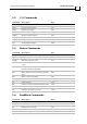
SimplIQ Command Reference Manual Functional Listing MAN-SIMCR (Ver. 4.5) Command Description Page PY Auxiliary position 3-120 VE Velocity error, in counts per second2 3-150 VX Main encoder velocity, in counts per second2 3-153 VY Velocity of auxiliary feedback 3-153 YA[N] Auxiliary position sensor parameters 3-165 2.
SimplIQ Command Reference Manual Functional Listing MAN-SIMCR (Ver. 4.5) Command Description Page UM Unit mode: stepper, torque control, speed control position control or dual loop 3-148 VH[N] High reference limit 3-151 VL[N] Low reference limit 3-151 XM[N] X Modulo 3-162 YM[N] Y Modulo 3-167 2.6 Communication Commands Command Description Page PP[N] Define the parameters of the CAN or RS232 communication 3-112 2.
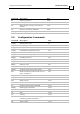
SimplIQ Command Reference Manual Functional Listing MAN-SIMCR (Ver. 4.5) 2.9 Data Recording Commands Command Description Page BH Get a sample signal as hexadecimal 3-11 RC Variables to record (two variables at each recording sequence) 3-122 RG Recording gap, in samples. Gap between consecutive data recordings. 3-123 RL Record length 3-124 RP[N] Recorder parameters 3-126 RR Recording on/off 3-128 RV[N] Recorded variables 3-130 YM[N] Auxiliary sensor modulo count 3-167 2.
SimplIQ Command Reference Manual Functional Listing MAN-SIMCR (Ver. 4.5) 2.
SimplIQ Command Reference Manual MAN-SIMCR (Ver. 4.5) Chapter 3: Alphabetical Listing This chapter lists all the commands in alphabetical order, along with detailed definitions and examples of each command. The description of each command includes the following items: Purpose: The operation or task of the command Attributes: The characteristics of the command Type: One of the following: A command: An instruction to do something.
SimplIQ Command Reference Manual Alphabetical Listing MAN-SIMCR (Ver. 4.5) Restrictions: The use of certain commands is illegal in certain contexts. The reasons for this may be: Safety: For example, it is not safe to change the direction of the feedback while the motor is running. Relevance: For example, a torque command cannot be specified in speed control mode (UM=2); in speed mode, the drive automatically sets the torque.
SimplIQ Command Reference Manual Alphabetical Listing MAN-SIMCR (Ver. 4.5) Limit Ranges The following table lists the value ranges for defining the limits of the system.
SimplIQ Command Reference Manual Alphabetical Listing MAN-SIMCR (Ver. 4.5) AB[N] – Absolute Encoder Setting Parameters Purpose: Configuration parameters for absolute sensor implementation of the SimplIQ drive series: Command Description AB[1] An absolute position resolution (number of abs. position readings) per analog signal cycle.
SimplIQ Command Reference Manual Alphabetical Listing MAN-SIMCR (Ver. 4.5) Attributes: Type: Source: Restrictions: Default values: Index range: Unit modes: Activation: Parameter, Integer Program, RS-232, CANopen MO=0 0, Non-volatile [1…6] All Immediate Note: The AB[N] parameters are usually programmed automatically by the Composer program. It is recommended that you avoid setting the AB[N] parameters manually.
SimplIQ Command Reference Manual Alphabetical Listing MAN-SIMCR (Ver. 4.5) AC - Acceleration Purpose: Defines the maximum acceleration in counts/second2. This parameter is used in speed mode (UM=2) and position control modes (UM=3, 4, 5) in PTP (PA, PR) and jogging (JV) reference modes. The AC parameter does not affect the present motion. It is used for planning the next motion, which is initiated by a BG command.
SimplIQ Command Reference Manual Alphabetical Listing MAN-SIMCR (Ver. 4.5) AG[N] - Analog Gains Array Purpose: Sets the gains for preconditioning analog signals, when RM = 1: AG[1] sets the gain of analog input #1 when used as a torque command (UM=1, 3). AG[2] sets the gain of analog input #1 when used as a speed command (UM=2). When RM = 0, the AG[N] parameters are ignored. The meaning of the analog gains depends on the unit mode, as shown in the following table.
SimplIQ Command Reference Manual Alphabetical Listing MAN-SIMCR (Ver. 4.5) AN[N] - Analog Inputs Array Purpose: AN[1] reports the analog input #1 value after offset correction (AS[1]), in volts. AN[2] reports the analog input #2 value after offset correction (AS[2]) in volts. AN[3] reports the measured current in the motor A phase, in amperes. AN[4] reports the measured current in the motor B phase, in amperes. AN[5] reports the measured current in the motor C phase, in amperes.
SimplIQ Command Reference Manual Alphabetical Listing MAN-SIMCR (Ver. 4.5) AS[N] - Analog Input Offsets Array Purpose: Compensates for offsets of the analog signals, which may be caused by the limited precision of the SimplIQ electronics. At times, the signals at the A/D converter may be offset: that is, the A/D reading may be non-zero when a zero reading is desired. This offset may disturb normal operation.
SimplIQ Command Reference Manual Alphabetical Listing MAN-SIMCR (Ver. 4.5) BG - Begin Motion Purpose: Immediately starts the next programmed motion. In software speed mode (UM=2), BG activates the latest JV, and also the new smooth factor (SF), acceleration (AC) and deceleration (DC). In stepper or position mode (UM=3, 4 or 5), BG starts the latest position mode programmed: a point-to-point motion (PA), a jogging motion (JV) or any type of tabulated motion (PVT or PT).
SimplIQ Command Reference Manual Alphabetical Listing MAN-SIMCR (Ver. 4.5) BH - Get a Single Recorded Signal as Hexadecimal Purpose: Uploads the values recorded by the recorder to a host. The BH command is designed to optimize data transfer from the drive to the host, assuming that the host has the computing power to analyze the drive message.
SimplIQ Command Reference Manual Alphabetical Listing MAN-SIMCR (Ver. 4.5) BP[N] - Brake Parameter Purpose: Defines the timing of the brake system in the motor when at least one of the digital outputs has been defined by the OL[N] command as a brake. For safety reasons, a brakeactive output releases the brake so that the brake is activated when the drive is not powered on. The brake output is always defined as active low.
SimplIQ Command Reference Manual Alphabetical Listing MAN-SIMCR (Ver. 4.5) BT - Begin Motion at Defined Time Purpose: Starts motion at the defined time. This command is designed to start the simultaneous motion of several axes. It is similar to the BG command with the following difference: BG starts motion immediately whereas BT begins at the defined time.
SimplIQ Command Reference Manual Alphabetical Listing MAN-SIMCR (Ver. 4.5) BV - Maximum Motor DC Voltage Purpose: Reports the scale factor for the drive bus voltage, in volts. This command indicates the type of power amplifier hardware.
SimplIQ Command Reference Manual Alphabetical Listing MAN-SIMCR (Ver. 4.5) CA[N] - Commutation Array Purpose: Defines motor and commutation parameters. The CA[N] array includes the parameters of the initial motor setup. The CA parameters need to be clearly defined in order to ensure that the motor rotates at all, and so that the feedback direction is correct. The CA[] array is typically programmed by the Elmo Composer during system configuration (by the wizard).
SimplIQ Command Reference Manual Alphabetical Listing MAN-SIMCR (Ver. 4.5) CA[12] Offset for the B (cosine) channel of the Analog Encoder, Resolver, Analog Halls or Absolute Coarse/Fine Encoder(fine mode). The offset is given in ADC units in the range of [-4500…4500]. CA[13] Relative gain of the A (sine) channel of the Analog Encoder, Resolver, Analog Halls or Absolute Coarse/Fine Encoder(fine mode) with respect to the B (cosine) channel in the range of [20000…40000].
SimplIQ Command Reference Manual Alphabetical Listing MAN-SIMCR (Ver. 4.5) CA[18] Feedback bits (“counts”) per revolution, after resolution is multiplied by 4, in the range [6…530,000,000]. - For Standard Incremental Encoders or Absolute encoders with Sin/Cosine signals with 1000 lines, CA[18] is 4000. If the motor is linear, CA[18] reflects the electrical cycle. For example, if the encoder has 1000 lines/m (4000 counts/m) and the distance between pole sets is 0.1 m, then CA[18] is 400.
SimplIQ Command Reference Manual Alphabetical Listing MAN-SIMCR (Ver. 4.5) CA[22] Main feedback type: 0: Reserved. 1: Main feedback entry used as input from a Resolver 2: Main feedback entry used as input for the quadrature incremental encoder signals. 3: Main feedback entry used as input for analog sine\cosine signal.
SimplIQ Command Reference Manual Alphabetical Listing MAN-SIMCR (Ver. 4.5) Command Description CA[27] Maximum acceptable number of iterations for auto-phasing process. If the process fails due to overload (motion amplitude is less than CA[24]), the auto-phasing may be repeated CA[27] times, with the current being doubled at every iteration. If the peak current (PL[1]) is reached at any attempt, the auto-phasing process will stop even if CA[27] allows more iterations.
SimplIQ Command Reference Manual Alphabetical Listing MAN-SIMCR (Ver. 4.5) CA[34] Configure resolver, analog halls or Absolute Coarse/Fine Encoder bits in the range of 10..16. The resolver / analog halls readout resolution is 216-CA[34] bits per resolver or analog halls cycle. For example, if CA[34]=4 the feedback reads 4096 bits per cycle. If the feedback has one pole pair, this will also be the bit count per mechanical revolution.
SimplIQ Command Reference Manual Alphabetical Listing MAN-SIMCR (Ver. 4.5) CC - Compiled Program Ready Purpose: Serves as the last stage of the user program downloading process, verifying a downloaded user program and marking it “ready for use.” The CC=N command specifies the program checksum. If this value coincides with the actual program checksum, the “Program ready” internal flag is set on. Otherwise, an error is returned.
SimplIQ Command Reference Manual Alphabetical Listing MAN-SIMCR (Ver. 4.5) CD - CPU Dump Purpose: Returns the status of the CPU and the database. Call CD if: The SR report indicates a CPU exception. The MF report indicates a CPU exception. An attempt to start the motor returns a “Bad database” error code.
SimplIQ Command Reference Manual Alphabetical Listing MAN-SIMCR (Ver. 4.5) “8” – indicates an unexpected error during an absolute position inquire. Verify hardware connection of the absolute feedback type. Attributes: Type: Source: Restrictions: Unit modes: Status report, String RS-232 None All Notes: If an LD command fails, CD reports the reason for the failure by adding the string “Couldn’t load from serial flash” followed by the reason for the failure.
SimplIQ Command Reference Manual Alphabetical Listing MAN-SIMCR (Ver. 4.5) CL[N] - Current Continuous Limitations and Motor Stuck Protection Parameters Purpose: Defines the continuous loading of the drive. CL[1] defines the maximum allowed continuous motor phase current, in amperes. This parameter is used to protect the motor from over-current, and the load from excessive torques. The motor current (torque) command is normally limited to its peak limit, as defined by PL[1].
SimplIQ Command Reference Manual Alphabetical Listing MAN-SIMCR (Ver. 4.5) Notes: The motor stuck protection is always applied to the main sensor. In dual loop applications, this protection does not pertain to failures in the auxiliary sensor. The time constant of 3 seconds is taken because almost every motion system applies high torques for short acceleration periods while the speed is slow. The minimum current limit is MC/128.
SimplIQ Command Reference Manual Alphabetical Listing MAN-SIMCR (Ver. 4.5) CP - Clear Program Purpose: Clears the entire user area in the serial flash memory. The CP instruction must be used before any attempt to write a new program to the drive. Attributes: Type: Source: Restrictions: Unit modes: Activation: Command, No value RS-232, CANopen MO=0, Program isn’t running All Immediate Notes: CP command execution may take a significant amount of time.
SimplIQ Command Reference Manual Alphabetical Listing MAN-SIMCR (Ver. 4.5) DC - Deceleration Purpose: Defines the maximum deceleration in counts/seconds2. This parameter is used in profiled speed control mode (UM=2, PM=1) and in position point-to-point (PA, PR) and jogging (JV) motions (UM=3, UM=4 and UM=5). The DC parameter does not affect the present motion. It is used to plan the next motion, initiated by a BG command.
SimplIQ Command Reference Manual Alphabetical Listing MAN-SIMCR (Ver. 4.5) DD - CAN Controller Status Purpose: Returns the status of the CAN controller as a string in hexadecimal form without a “0x” prefix. DD is valid only for drives that support CAN controllers.
SimplIQ Command Reference Manual Alphabetical Listing MAN-SIMCR (Ver. 4.5) DF/DS - Download Firmware Purpose: Downloads a new firmware version. These commands are designed as part of a sequence that is normally performed and controlled by the Composer program, which reads the firmware update file provided by Elmo, and performs a sequence of actions that includes the DF/DS command. Notes: After new firmware is downloaded, the drive reboots. All data stored in temporary variables in the RAM is lost.
SimplIQ Command Reference Manual Alphabetical Listing MAN-SIMCR (Ver. 4.5) DL - Download Program Purpose: Downloads data to the serial flash memory of the drive. The DL command is used primarily to download compiled user programs to the drive. The format of a DL command is: DL##[hex binary data][esc]checksum] Notes: The DL command is normally activated and used by the Composer software. The command should not be used manually.
SimplIQ Command Reference Manual Alphabetical Listing MAN-SIMCR (Ver. 4.5) DV[N] - Reference Desired Value Purpose: Reports the reference commands to the position, speed and current controllers of the drive. DV[N] reports the final value of the controller references, as synthesized by all their sources: software reference generators, external reference inputs and external control loops. For UM=1, DV[1] reports the torque command. DV[2] and DV[3] report zero.
SimplIQ Command Reference Manual Alphabetical Listing MAN-SIMCR (Ver. 4.5) EC - Error Code Purpose: Reports the processing status of the last accepted command that returned an error. Notes: When the processing of a command fails, the error code is returned immediately with a question mark in the response to that command. The error code returned with the command response is binary, so it may not be easily seen. The EC command returns a printable (ASCII) value of the error code.
SimplIQ Command Reference Manual Alphabetical Listing MAN-SIMCR (Ver. 4.5) Error Code Error String / Description Example / Remedy 12 Command not available in this unit mode. PA=1000 is an error if UM=2, because the position command cannot be given in this mode. 13 Cannot reset communication – UART is busy. Modification of the parameters of the serial communication has been attempted while the communication line is busy. 18 Empty assign. The right side of an equation is missing.
SimplIQ Command Reference Manual Alphabetical Listing MAN-SIMCR (Ver. 4.5) Error Code Error String / Description Example / Remedy 28 Out of limit range. A command was specified out of its permitted limits. VH[2]=1000; SP=2000 is an error because the latter command specifies that point-to-point motions should reach the speed of 2000 counts/sec, whereas the first command limits the maximum speed command to 1000. 30 No program to continue.
SimplIQ Command Reference Manual Alphabetical Listing MAN-SIMCR (Ver. 4.5) Error Code Error String / Description Example / Remedy 45 Returned error from subroutine. Occurs when a return op-code has no valid address to return to. 46 May not use multi-capture homing mode with stop event. Occurs when trying to set multiple capture events with a STOP between events. 47 User program does not exist. XQ or XC returns this error if a program has not been loaded to and successfully verified by the drive.
SimplIQ Command Reference Manual Alphabetical Listing MAN-SIMCR (Ver. 4.5) Error Code Error String / Description Example / Remedy 57 Motor must be off. This command cannot be used when the motor is on. CA[25]=1 sets the order of firing the motor phases, thereby controlling the motor direction. This parameter cannot be set while the motor is on, because it will immediately destabilize the feedback loop. 58 Motor must be on. This command cannot be used when the motor is off.
SimplIQ Command Reference Manual Alphabetical Listing MAN-SIMCR (Ver. 4.5) Error Code Error String / Description Example / Remedy 70 Recorder data invalid. Cannot upload recorded data because the recorder contains no valid data. Recorder settings (such as RC=n) have been changed since the last records were made or the recorder has not been operated at all since power up. 71 Homing is busy. Cannot change the modulo count (XM or YM) while homing is in progress.
SimplIQ Command Reference Manual Alphabetical Listing MAN-SIMCR (Ver. 4.5) Error Code Error String / Description Example / Remedy 90 CAN state machine is not ready (object 0x6041 on DS402). Set the drive to the “Switched on” state machine by setting the relevant transitions to the control word, object 0x6040. Refer to the description of NMT services in the Elmo CANopen Implementation manual. 93 There is a wrong initiation value for this command. Reset queue length before updating queries.
SimplIQ Command Reference Manual Alphabetical Listing MAN-SIMCR (Ver. 4.5) Error Code Error String / Description Example / Remedy 111 KV[N] vector is invalid. Invalid values in KV[N] parameters. Refer to the “Advanced Filter” chapter in the SimplIQ Software Manual. If the vector was configured by the Composer auto-tuning wizard, email Technical Support for assistance. 112 KV[N] defines scheduled block but scheduling is off. Invalid values in KV[N] parameters.
SimplIQ Command Reference Manual Alphabetical Listing MAN-SIMCR (Ver. 4.5) Error Code Error String / Description Example / Remedy 127 Modulo range must be positive. XM[2] is less or equal to XM[1] or YM[2] is less or equal to YM[1]. 128 Bad variable index in database - internal compiler error. Index of the variable in the database is not correct. An internal compiler error occurs due to a corrupted database. In such a case, email Technical Support for assistance.
SimplIQ Command Reference Manual Alphabetical Listing MAN-SIMCR (Ver. 4.5) Error Code Error String / Description Example / Remedy 137 Program already compiled. An attempt was made to download a user program before previous one was erased. Use the CP command before downloading a new user program. 139 The number of breakpoints exceeds the maximum number. 140 An attempt to set/clear breakpoint at the non-relevant line. Internal IDE error. 141 Boot identity parameters section is not clear.
SimplIQ Command Reference Manual Alphabetical Listing MAN-SIMCR (Ver. 4.5) Error Code Error String / Description Example / Remedy 147 Executable command within math expression. An attempt has been made to assign an executable command. BG=3; is wrong because BG is an executable command and cannot be assigned. 148 Nothing in the expression. An attempt has been made to evaluate an empty expression. AC=; is wrong because the assign value is missing. 149 Unexpected sentence termination.
SimplIQ Command Reference Manual Alphabetical Listing MAN-SIMCR (Ver. 4.5) Error Code Error String / Description Example / Remedy 156 Bad opcode. Compiled code contains mismatched addressing mode. Internal compiler error caused by corrupted compiled code. In this case, email Technical Support for assistance. Attach Composer date and version (in Help menu) and program you tried to compile. 157 No available program stack. An attempt was made to run too many user programs simultaneously.
SimplIQ Command Reference Manual Alphabetical Listing MAN-SIMCR (Ver. 4.
SimplIQ Command Reference Manual Alphabetical Listing MAN-SIMCR (Ver. 4.5) EF[N] - Encoder Filter Frequency Purpose: Filters encoder signal in order to improve its noise immunity. Because the logic of the quadrature decoder must sense transitions, the inputs are first run through a glitch filter. This filter has a digital delay line that samples four time points on the signal and verifies that a majority of the samples are at a new state before outputting the new state to the internal logic.
SimplIQ Command Reference Manual Alphabetical Listing MAN-SIMCR (Ver. 4.5) In the above example, make the following assumptions: • An interpolated encoder is used. • The maximum speed of the motor remains 10,000 rpm. • The motor is equipped with an interpolated encoder with 2048 analog sine/cosine periods per mechanical revolution. • The interpolation x32 (CA[31]=5) is used. • The feedback resolution is formed as 2048 * 2 = 65536 counts / rev .
SimplIQ Command Reference Manual Alphabetical Listing MAN-SIMCR (Ver. 4.5) EM[N] - ECAM Parameters Purpose: Determines the behavior of ECAM (Electronic CAM) motions. With ECAM, the position reference to the drive is not directly proportional to the summed external inputs, but is rather a function of them. The ECAM parameters apply only to position modes (UM=3 and 5) and when the position reference is derived from the auxiliary encoder input (RM=1, FR[3]=non-zero).
SimplIQ Command Reference Manual Alphabetical Listing MAN-SIMCR (Ver. 4.
SimplIQ Command Reference Manual Alphabetical Listing MAN-SIMCR (Ver. 4.5) EO - Echo Mode Purpose: Sets or resets the communication echo mode, which is used for communication checks. EO=1 enables echo mode EO=0 disables it. With RS-232 communication, the EO command sends an immediate echo character for every terminal character. The echo transmission is deferred to the command response string.
SimplIQ Command Reference Manual Alphabetical Listing MAN-SIMCR (Ver. 4.5) ER[N] - Maximum Tracking Error The Tracking Error is the difference between the command and its feedback. Purpose: ER[2] defines the maximum allowed velocity error (abs(DV[2]-VX)) in counts/second. If the error exceeds this value, the motor is automatically disabled and the Error Limit fault is activated.
SimplIQ Command Reference Manual Alphabetical Listing MAN-SIMCR (Ver. 4.5) ET[N] - Entries for ECAM Table Purpose: In the ECAM process, the position reference is set to a tabulated function, called the ECAM function, of the external inputs. The ET[N] vector stores the tabulated values of the ECAM function.
SimplIQ Command Reference Manual Alphabetical Listing MAN-SIMCR (Ver. 4.5) FF[N] - Feed Forward Purpose: Defines how much of the position reference derivative is fed as a reference to the speed controller. For most UM=5 applications, FF[2]=1. For most UM=4 applications, FF[2] is the number of counts traveled by the main (speed) feedback, while the position (auxiliary) feedback travels one count.
SimplIQ Command Reference Manual Alphabetical Listing MAN-SIMCR (Ver. 4.5) FR[N] - Follower Ratio Purpose: FR[1] defines the follower ratio for current (UM=1). FR[2] defines the follower ratio for velocity (UM=2). FR[3] defines the follower ratio for position (UM=3, 5). When UM=1, the auxiliary reference is composed of the analog input and external PWM signals. The FR[1] parameter scales the ratio between the Duty Cycle of the PWM signal and the reference to the current loop (UM=1, RM=1).
SimplIQ Command Reference Manual Alphabetical Listing MAN-SIMCR (Ver. 4.5) GS[N] - Gain Scheduling Purpose: Defines the gain scheduling process. SimplIQ drives are scheduled according to the controller and the command states. This may be necessary due to either the difference between the low-speed behavior and the high-speed behavior of the plant or because the inertia changes with position dependence.
SimplIQ Command Reference Manual Alphabetical Listing MAN-SIMCR (Ver. 4.
SimplIQ Command Reference Manual Alphabetical Listing MAN-SIMCR (Ver. 4.5) HL[N] - Over-speed Limit and Position Range Limit Refer to LL[N] - Low Feedback Limit.
SimplIQ Command Reference Manual Alphabetical Listing MAN-SIMCR (Ver. 4.5) HM[N] - Homing, Capture and Flag Purpose: Sets the parameters of the main homing and capture process, by which the drive sets a trap for a user-defined event. When the event occurs, the SimplIQ can: Modify a position counter (homing) Log the exact position of the event (capture) Flag a digital output (flag) An event is a change in a digital input signal. The polarity of the change is defined by the IL[N] command.
SimplIQ Command Reference Manual Alphabetical Listing MAN-SIMCR (Ver. 4.5) HM[N] (Index) Value Description 0 4 After-event behavior. Defined 1 as the time in 2 which HM[1] decreases to 0. In UM=2, 3, 4, 5: Stop immediately using SD deceleration value. In torque mode (UM=1), do nothing. 0 5 What to set for PX 1 during event Absolute setting of position counter: PX=HM[2]. 2 Set digital output, equivalent to OP=HM[6]. Do nothing.
SimplIQ Command Reference Manual Alphabetical Listing MAN-SIMCR (Ver. 4.5) When the Index or Home signal captures PX, the PY captured value is taken at the next position controller sampling time (4 TS period). It may differ from the PY value at the capture time by up to 4*TS*10-6*VY counts. When the Index or Home signal captures PX, the digital output of HM[6] is set only at the next position controller sampling time (4 TS period).
SimplIQ Command Reference Manual Alphabetical Listing MAN-SIMCR (Ver. 4.5) HP - Halt Program Execution Purpose: Stops the execution of the user program and the automatic routines. The HP command freezes the status of the program and does not reset it. A later XC command will resume the program from the instruction at which the program was halted. Pending interrupts will remain pending. An HP command issued when no program is running does nothing and sets no error code.
SimplIQ Command Reference Manual Alphabetical Listing MAN-SIMCR (Ver. 4.5) HX - Hexadecimal Mode Purpose: Sets or resets the hexadecimal mode for reporting integer parameter values. With HX=0, integers are reported as decimal numbers. With HX=1, integers are reported as hexadecimal numbers. HX does not affect floating-point reports.
SimplIQ Command Reference Manual Alphabetical Listing MAN-SIMCR (Ver. 4.5) HY[N] - Auxiliary Homing, Capture and Flag Purpose: Sets the parameters of the auxiliary homing and capture process, by which the SimplIQ sets a trap for a user-defined event. When the event occurs, the drive can: Modify the auxiliary position counter (homing) Log the exact position of the event (capture) Flag a digital output (flag) An event is a change in a digital input signal.
SimplIQ Command Reference Manual Alphabetical Listing MAN-SIMCR (Ver. 4.5) HY[N] (Index) Value 5 0 What to set for PY 1 during event 2 Description Absolute setting of position counter: PY=HY[2]. Relative setting of position counter: PY = PY (at event) -HY[2] Do nothing. 6 Output value Digital output value if HY[4]=1. Only outputs defined as general output are affected. 7 PY captured value Captured value of PY, before any modification by the HY[N] command (read only).
SimplIQ Command Reference Manual Alphabetical Listing MAN-SIMCR (Ver. 4.
SimplIQ Command Reference Manual Alphabetical Listing MAN-SIMCR (Ver. 4.5) IB[N] - Input Bits Array Purpose: Provides read access to digital input bits. IB[N] reports the status of the corresponding input bits, according to the definition in IP. If IB[N] is “1”, the corresponding Nth bit in IP is logically active. Use the IB[N] command to reference general purpose inputs, limit switches and other indications (such as Stop, Begin or Enable) individually.
SimplIQ Command Reference Manual Alphabetical Listing MAN-SIMCR (Ver. 4.5) ID, IQ - Read Active Current and Reactive Current Purpose: Gets the active (IQ) and the reactive (ID) components of the motor current, in amperes. A brushless motor carries alternating currents in its phases. The alternating currents in the motor phases create a rotating magnetic field, which can be projected in two directions.
SimplIQ Command Reference Manual Alphabetical Listing MAN-SIMCR (Ver. 4.5) IF[N] - Digital Input Filter Purpose: Filters the drive digital inputs in order to overcome switch bounding. IF[N] defines a time period in milliseconds. Input pulses of shorter duration than IF[N] are rejected. Pulses longer than IF[N] in milliseconds are sensed. Each index entry [1 - 10] refers to a digital input [1 - 10] respectively. The input filtering is accomplished by the software.
SimplIQ Command Reference Manual Alphabetical Listing MAN-SIMCR (Ver. 4.5) IL[N] - Input Logic Purpose: Defines the logic level and functional behavior of the digital inputs. The drive has several non-committed digital inputs. Each of these inputs can be programmed to a specific function and logic level. In addition, the IL[N] function enables the simulation of a digital input. This option is convenient for testing and debugging user programs.
SimplIQ Command Reference Manual Alphabetical Listing MAN-SIMCR (Ver. 4.5) IL[N] Bits Meaning Values 0 0: Low level active. The function attached to this switch is activated when no current flows through the input opto-coupler. Logic levels 1: High level active. The function attached to this switch is activated when current flows through the input opto-coupler. 1-4 Function behaviors (next table) 0: Inhibit (INH); shut servo driver, freewheel.
SimplIQ Command Reference Manual Alphabetical Listing MAN-SIMCR (Ver. 4.5) Command Value Active Level When Active . . . IL[N]=0 Low Shut servo drive, freewheel. IL[N]=1 High Shut servo drive, freewheel Note: It is high recommended not to use this state. The motor may spin when the input wire is cut or disconnected. IL[N]=2 Low Stop immediately under control: soft and auxiliary stop. IL[N]=3 High Stop immediately under control: soft and auxiliary stop. IL[N]=4 Low No function is attached.
SimplIQ Command Reference Manual Alphabetical Listing MAN-SIMCR (Ver. 4.5) Function 0: Inhibit (freewheel) Servo is off (MO=0). The motor is not under control. No current is applied through the motor phases. If the motor was previously running, it will continue to coast on its own inertia. The motor fault code (see the MF command) is 0x10.
SimplIQ Command Reference Manual Alphabetical Listing MAN-SIMCR (Ver. 4.5) Function 5: Hard-forward limit switch The function activates the ##AUTO_FLS routine in the user program. In addition, it has the following unit mode dependent actions. UM Action Torque (UM=1) Allow only negative torque commands. Positive torque demands yield zero motor current. Speed (UM=2) Allow only negative speed command (internal or external).
SimplIQ Command Reference Manual Alphabetical Listing MAN-SIMCR (Ver. 4.5) Function 8: Main Home switch This function activates the ##AUTO_HM routine in the user program. When the function is selected, digital input connector pin #5 serves as the Home/Capture switch for the feedback defined as main. Only IL[5] can be programmed to this function. Refer to the HM[N] command for more information. Function 9: Auxiliary Home switch This function activates the ##AUTO_HY routine in the user program.
SimplIQ Command Reference Manual Alphabetical Listing MAN-SIMCR (Ver. 4.5) When a switch is released, the attached function terminates. Functions 2, 3 and 4 (Full Stop, RLS and FLS) do not change the drive reference command. When the switch is released, the reference command (speed or position) is recovered. In order to ensure that reference recoveries do not generate discontinuities, the SD, VL[2] and VH[2] limits are used.
SimplIQ Command Reference Manual Alphabetical Listing MAN-SIMCR (Ver. 4.5) IP - Input Port Purpose: Reports an active or non-active state of a digital input. A digital input is considered to be active when the associated function is logically active. The functionality and logic levels are defined in the IL[N] command. IP logic is always positive. When the digital input is active, the relevant IP bit is set.
SimplIQ Command Reference Manual Alphabetical Listing MAN-SIMCR (Ver. 4.5) Notes: Each type of Elmo drive supports a different number of digital inputs. Please consult the drive’s Installation Guide for more information about its inputs. For compatibility reason inputs 7-10 do not have an indication for the “General Purpose” function and cannot be used for user program AUTO routine as well. Bits 22-25 will still be set regardless to the above.
SimplIQ Command Reference Manual Alphabetical Listing MAN-SIMCR (Ver. 4.5) JV- Jogging Velocity Purpose: Sets the motor speed. In speed control mode (UM=2), the JV parameter specifies the software speed command. In un-profiled mode (PM=0), the speed command is set to JV immediately. In profiled mode (PM=1), the speed command is gradually changed to JV, according to the AC, DC and SF parameters. In the position control modes (UM=4, 5), the JV setting defines a constant speed software command.
SimplIQ Command Reference Manual Alphabetical Listing MAN-SIMCR (Ver. 4.5) KG[N] - Gain Scheduled Controller Parameters Purpose: Specifies the parameters of the gain scheduled speed or position controller. The KG[N] parameters apply only if the controller gains are scheduled (GS[2]=64).
SimplIQ Command Reference Manual Alphabetical Listing MAN-SIMCR (Ver. 4.5) KI[N], KP[N] - PI Parameters Purpose: KI[1], KP[1] defines the PI current control filter. KI[2], KP[2] defines the PI velocity control filter. KP[3] defines the gain of the position controller. The parameters KP[2], KI[2] and KP[3] apply only if the controller gains are fixed (gain scheduling is not used: GS[2]=0).
SimplIQ Command Reference Manual Alphabetical Listing MAN-SIMCR (Ver. 4.5) KL - Kill Motion and Program Purpose: Halts program execution and stops the motor. The KL command stops the execution of the user program threads and automatic routines. It also issues the MO=0 motor disable command. KL freezes the status of the program and does not reset it. A later XC command will resume the program from the instruction at which the program was halted. Pending interrupts will remain pending.
SimplIQ Command Reference Manual Alphabetical Listing MAN-SIMCR (Ver. 4.
SimplIQ Command Reference Manual Alphabetical Listing MAN-SIMCR (Ver. 4.5) LC - Current Limit Flag Purpose: Reports the status of the current limiting process. You may select two different current limit specifications: The peak limit PL[1] specifies how much current can be applied to the motor for short time periods (PL[2]) and the continuous limit CL[1] specifies how much current can be applied to the motor continuously.
SimplIQ Command Reference Manual Alphabetical Listing MAN-SIMCR (Ver. 4.5) LD - Load Parameters from Flash Purpose: Loads all non-volatile variables from the flash memory to the RAM and resets all volatile variables to their default values. Before accepting the loaded parameters, LD tests them as follows: The variables written in the flash memory can be read. The variables cannot be read if the flash memory is brand new and no parameters have ever been saved in it, or after a major firmware update.
SimplIQ Command Reference Manual Alphabetical Listing MAN-SIMCR (Ver. 4.5) LL[N] - Low Feedback Limit Purpose: Speed limits The parameters LL[2] and HL[2] define the limits of the allowed motor speed.
SimplIQ Command Reference Manual Alphabetical Listing MAN-SIMCR (Ver. 4.5) LP[N] - List Properties Purpose: Sets the properties of the serial flash data upload and download by the next LS and DL commands. LP[1] sets the start byte address of the next LS transmission, or the byte address for starting the storage of the next DL transmission. LP[2] sets the size — in bytes — to be transmitted at the next LS. LP[3] returns the start byte address of the user program (read only).
SimplIQ Command Reference Manual Alphabetical Listing MAN-SIMCR (Ver. 4.5) LS - List User Program Purpose: Uploads data from the serial flash to the host, according to the parameters of LP[N]. The most common use of LS is to retrieve the user program and to retrieve the personality (firmware partition) data of the drive. LS begins to send data from the byte address of LP[1] in the serial flash memory. The length of the transmitted data is LP[2] bytes.
SimplIQ Command Reference Manual Alphabetical Listing MAN-SIMCR (Ver. 4.5) MC - Maximum Peak Driver Current Purpose: Reports the maximum phase current allowed for the drive, in amperes. This command informs the software about the type of servo drive used with the controller. Attributes: Type: Source: Restrictions: Unit modes: Report, Real Program, RS-232, CANopen Read only All You may limit the current for a specific application using the PL[1] and CL[1] commands.
SimplIQ Command Reference Manual Alphabetical Listing MAN-SIMCR (Ver. 4.5) MF - Motor Failure Purpose: Reports the reason why the motor has been automatically shut down (set to MO=0). MF normally reports zero (as default). The fact that the motor has been automatically shut down is reflected as a bit in the status register (SR) report, and MF provides the detailed information. After a fault, the MF value remains fixed, even if the reason for the fault no longer exists.
SimplIQ Command Reference Manual Alphabetical Listing MAN-SIMCR (Ver. 4.5) Reported Fault Value Bit Cannot start because of inconsistent database. The type of database inconsistency is reflected in the status SR report, and in the CD CPU dump report. 0x200 9 Too large a difference in ECAM table. 0x400 10 Heartbeat failure. Error occurs only if drive is set to abort under heartbeat failure in a CANopen network (object 0x6007 in CAN object dictionary is set to 2). 0x800 11 Servo drive fault.
SimplIQ Command Reference Manual Alphabetical Listing MAN-SIMCR (Ver. 4.5) 0x8000 0x4000 0x2000 Meaning 0 0 0 OK. 0 0 1 Under voltage. The power supply is shut down or it has too high an output impedance. 0 1 0 Over voltage. The voltage of the power supply is too high, or the servo drive did not succeed in absorbing the kinetic energy while braking a load. A shunt resistor may be required. 0 1 1 Reserved. 1 0 0 Reserved. 1 0 1 Short circuit.
SimplIQ Command Reference Manual Alphabetical Listing MAN-SIMCR (Ver. 4.5) MI - Mask Interrupt Purpose: Selects which interrupts (automatic routines) are active. A user program may include a main code and some automatic routines. When the program runs, the conditions for calling these routines are checked continuously. If the conditions for running a automatic routine 4 are met, it is called. At certain times, you may want to block some of the automatic routines.
SimplIQ Command Reference Manual Alphabetical Listing MAN-SIMCR (Ver. 4.5) Notes: MI is not affected by the XQ command. You should set MI to the desired value in the first lines of your user program in order to ensure that the correct automatic routines can run. Several interrupts may be blocked by the MI command. MI=65,535 or MI=0xffff will block all interrupts of the table. MI=48 will block only the AUTO_FLS and the AUTO_RLS interrupts.
SimplIQ Command Reference Manual Alphabetical Listing MAN-SIMCR (Ver. 4.5) MO - Motor Enable/Disable Purpose: Enables and disables (freewheels) the motor power. Disabling the motor MO=0 disables the motor. This is the idle state of the drive. The power stage is disabled and no current flows in the motor.
SimplIQ Command Reference Manual Alphabetical Listing MAN-SIMCR (Ver. 4.5) In encoder-only systems (in which no digital Hall sensors are present), the commutation is calculated only once after power up upon the first MO=1 command. The motor moves a few encoder counts during the automatic commutation search. When the brake function is enabled, the dedicated output is released after the duration defined in BP[N]. During this time, all motion reference commands are ignored.
SimplIQ Command Reference Manual Alphabetical Listing MAN-SIMCR (Ver. 4.5) MP[N] - Motion (PT/PVT) Parameters Purpose: Programs the parameters of PVT or PT motions. PT or PVT motion is programmed as a sequence of points that are visited at programmed times. The QP[N] array stores the position reference points used for PT or PVT motion. The QV[N] and QT[N] arrays store the speed and timing data that is additionally required for PVT motions.
SimplIQ Command Reference Manual Alphabetical Listing MAN-SIMCR (Ver. 4.5) MP[1] and MP[2] cannot be changed during a PT or PVT motion.
SimplIQ Command Reference Manual Alphabetical Listing MAN-SIMCR (Ver. 4.5) MS - Motion Status Purpose: Reports the status of the motion profiling process. MS can be used for detecting the end of motions: a PTP motion that has reached its target, or a completed PT or PVT motion. For position control modes (UM=3, 4, 5), MS reports as follows: Value Description 0 Motor position stabilized. The feedback position is steady within the ranges defined by TR.
SimplIQ Command Reference Manual Alphabetical Listing MAN-SIMCR (Ver. 4.5) OB[N] - Output Bits Array Purpose: Sets and resets an output bit. The OB[N] command only sets a digital output that is defined by OL[N] as a general purpose output. OB[N] for N=1…6 returns the value of digital output (N), if digital output N is defined as general purpose output. Otherwise, it returns 0. OB[10…15] are reserved.
SimplIQ Command Reference Manual Alphabetical Listing MAN-SIMCR (Ver. 4.
SimplIQ Command Reference Manual Alphabetical Listing MAN-SIMCR (Ver. 4.5) OC[N] – Output Compare Purpose: Output a signal when the present position is compared to a user defined position. The OC command generates a train of pulses according to the encoder position values. The OC[1] command operates in two modes: 1. OC[1]=1: Absolute position mode. The first pulse is generated by the initialized absolute position defined by OC[2] (i.e.
SimplIQ Command Reference Manual Alphabetical Listing MAN-SIMCR (Ver. 4.5) -1: No more pulses are being generated because the number of pulses specified in OC[5] has been reached. 0: Output Compare function is disabled. 1: a. Output Compare at absolute position: Output Compare function has started but absolute position has not yet been reached; therefore, the train of pulses has not begun. b.
SimplIQ Command Reference Manual Alphabetical Listing MAN-SIMCR (Ver. 4.5) Attributes: Type: Source: Restrictions: Parameter, Integer Program, RS-232, CANopen None Default values: OC[1]…OC[2], OC[5]…OC[6]=0 , OC[3]=100(RS), volatile OC[4]=200(RS), volatile Range: OC[1]: [0…2] OC[2]: [-109 … 109] OC[3]: [-65,535 …65,535], excluding 0,-1,1 OC[4]: [1…65,535] OC[5]: [0…65,535] OC[6]: [0..
SimplIQ Command Reference Manual Alphabetical Listing MAN-SIMCR (Ver. 4.5) OL[N] - Output Logic Purpose: Defines the logic level and function behavior of the digital outputs. The drive has several non-committed digital outputs (2 in the Harmonica and Bassoon, 5 in the Cello, 6 in the Cornet). Each of these outputs can be programmed to a specific function and logic level.
SimplIQ Command Reference Manual Alphabetical Listing MAN-SIMCR (Ver. 4.5) The possible values of OL[N] are outlined in the following table. Command Value Active Level When Active . . . OL[N]=0 Low Output serves as general purpose. OL[N]=1 High Output serves as general purpose. OL[N]=2 Low AOK: drive ready for use. OL[N]=3 High AOK: drive ready for use. OL[N]=4 Low Brake feature is active.
SimplIQ Command Reference Manual Alphabetical Listing MAN-SIMCR (Ver. 4.5) OP - Output Port Purpose: Sets values for all uncommitted digital outputs, defined as general purpose by the OL[N] command. OP does not affect the digital output pins otherwise defined. The bits of OP[N] can be individually accessed by OB[N]. For more information, refer to the OB[N] and OL[N] commands.
SimplIQ Command Reference Manual Alphabetical Listing MAN-SIMCR (Ver. 4.5) PA - Absolute Position Purpose: Specifies that the next software position command will be a PTP (point-to-point) and defines the target position for the next PTP motion. The position reference to the drive is composed of an “internal” software command and an external command, calculated from the analog inputs and the auxiliary feedback input.
SimplIQ Command Reference Manual Alphabetical Listing MAN-SIMCR (Ver. 4.5) PE - Position Error Purpose: Returns the present position tracking error, in counts. In main feedback position mode (UM=5), PE reads: PE = DV[3] – PX. PE is read modulo-XM[N], taken the shorter way. For example, if XM[1]=-500, XM[2]=500, DV[3]=400 and PX=-400, PE will read 200. In auxiliary feedback position mode (UM=4), PE reads: PE = DV[3] – PY. PE is read modulo-YM[N], taken the shorter way.
SimplIQ Command Reference Manual Alphabetical Listing MAN-SIMCR (Ver. 4.5) PK - Peak Memory Purpose: Returns the DSP memory dump for an address range. Syntax: PK=N where N is a 32-bit number whose least significant 24 bits contain the starting DSP memory address and the most significant eight bits contain the data length. The data length is limited to 128 words, due to the limitation of the output buffer. If the data length is 0, 128 or greater, the PK command returns 128 words by default.
SimplIQ Command Reference Manual Alphabetical Listing MAN-SIMCR (Ver. 4.5) PL[N] - Peak Duration and Limit Purpose: PL[1] defines the motor maximum peak current, in amperes. PL[2] defines the motor maximum peak duration, in seconds. This parameter is used to protect the motor (or the drive) from over-current, and to protect the load from excessive torque. The motor current (torque) command is normally limited to its peak limit, as defined by PL[1].
SimplIQ Command Reference Manual Alphabetical Listing MAN-SIMCR (Ver. 4.5) If, prior to the high current demand, the current demand was very close to CL[1], the switch will occur almost instantaneously. If the current demand is marginally greater than CL[1], and significantly less than PL[1], the switch may take a very long time. The exact time required may be calculated from the previous formulas. If CL[1] > PL[1], PL[1] will be the torque limit in effect at all times, and PL[2] will be ignored.
SimplIQ Command Reference Manual Alphabetical Listing MAN-SIMCR (Ver. 4.5) PM - Profiler Mode Purpose: Specifies, in UM=2, if the software speed command generator applies acceleration, deceleration and smoothing limits. The values of PM are outlined in the following table: PM Value Description 0 For UM=2, AC, DC and SF are not used. 1 For UM=2, AC, DC and SF are used normally. Table 3-36: PM Values PM=0 is set by the Composer program to test the step response of the speed controller.
SimplIQ Command Reference Manual Alphabetical Listing MAN-SIMCR (Ver. 4.5) PP[N] - Protocol Parameters Purpose: Programs all communication parameters. The PP[N] command has independent fields for the parameters of all supported communication methods. These parameters are tabulated in the tables that follow. Parameter Description Range PP[1] Type of communication. PP[1] serves as “Enter Communication Parameters” for RS-232. PP[2] and PP[4] come into effect only when PP[1] is written.
SimplIQ Command Reference Manual Alphabetical Listing MAN-SIMCR (Ver. 4.5) Attributes: Type: Source: Restrictions: Default values: Range: Index range: Unit modes: Activation: Parameter, Integer RS-232, CANopen MO=0 for PP[1] PP[1]=1, PP[2]=2, PP[13]=127, PP[14]=1, PP[15]=128 All others default to zero (RS), Non-volatile As shown in previous tables [1…15] All RS-232 parameters activated by setting PP[1].
SimplIQ Command Reference Manual Alphabetical Listing MAN-SIMCR (Ver. 4.5) PR - Relative Position Purpose: Specifies that the next software position command will be a PTP (point-to-point) motion and defines its target position (refer to the PA command). PR may be applied in any active motion mode; it is activated and applies changes to the PA setting only after the next BG is executed. If PTP motion is already active, PA will be increased by the PR value and become the new position target.
SimplIQ Command Reference Manual Alphabetical Listing MAN-SIMCR (Ver. 4.5) PS - Program Status Purpose: Returns the status of the user program. If a user program is running, PS returns the number of user program threads: 0 if the user program is halted –1 if no user program thread is running –2 if no user program is ready to run For detailed information about the status of the user program threads, use the DB command.
SimplIQ Command Reference Manual Alphabetical Listing MAN-SIMCR (Ver. 4.5) PT - Position Time Command Purpose: Specifies that the next BG will start a PT (Position - Time) tabulated motion and defines the starting index in the QP[N] array. In a PT motion, a new position reference value is picked from the QP[N] array once per MP[4] position controller sampling times. The motion is interpolated between the points specified by the QP[N] array.
SimplIQ Command Reference Manual Alphabetical Listing MAN-SIMCR (Ver. 4.5) PV - Position Velocity Time Command Purpose: Specifies that the next BG will start a PVT (Position - Velocity - Time) tabulated motion and defines the starting index for the QP[N], QV[N] and QT[N] arrays. In a PVT motion, new position and speed reference values are picked from the QP[N] and QV[N] arrays at the time specified by the elements of the QT[N] array. The motion is interpolated between the entries of QP[N] and QV[N].
SimplIQ Command Reference Manual Alphabetical Listing MAN-SIMCR (Ver. 4.5) PW[N] - PWM Signal Parameters Purpose: PW[1] defines the offset value for PWM signals in fractions of the Duty cycle. PW[2] defines the dead band zone of the PWM signal in the fractions of the Duty cycle. At times, the application requires the Duty cycle value to be different from the source of the PWM signals (i.e. offset). The PW[1] parameter is intended for this purpose.
SimplIQ Command Reference Manual Alphabetical Listing MAN-SIMCR (Ver. 4.5) PX - Main Position Purpose: Reads the position of the main feedback. Upon power on, the main position is set to zero. The variable PX accumulates the main feedback pulses. PX can count cyclically (refer to the XM[N] command). When the motor is off, PX may be used to set a value for the position counter by typing PX=n. To program the position while the motor is on, refer to the HM[N] command.
SimplIQ Command Reference Manual Alphabetical Listing MAN-SIMCR (Ver. 4.5) PY - Auxiliary Position Purpose: Reads the position of the auxiliary feedback. Upon power on, the auxiliary position is set to zero. The variable PY accumulates the auxiliary feedback pulses. PY can count cyclically (refer to the YM[N] command). When the motor is off, PY may be used to set a value for the auxiliary position counter by typing PY=n. To program PY while the motor is on (MO=1), refer to the HY[N] command.
SimplIQ Command Reference Manual Alphabetical Listing MAN-SIMCR (Ver. 4.5) QP[N], QT[N], QV[N] - Position, Time, Velocity Purpose: Stores data for the PT and PVT motion modes. The QP[N], QV[N] and QT[N] arrays define the position (QP[N]) and speed (QV[N]) at any single time instance (QT[N]). With CANopen communication, the QP[N], QV[N] and QT[N] arrays can be programmed at high speed using specially designed communication objects.
SimplIQ Command Reference Manual Alphabetical Listing MAN-SIMCR (Ver. 4.5) RC - Define Recorded Variables Purpose: Defines which signals are to be recorded. The drive can record a range of signals for performance verification and debugging. The first step of the recording process is the definition of the recorded variable by assigning a value to RC, a bit field. Each “on” bit in the binary representation of RC defines a signal to be recorded.
SimplIQ Command Reference Manual Alphabetical Listing MAN-SIMCR (Ver. 4.5) RG - Recorder Gap Purpose: Defines the frequency per sampling times that the recorder is activated. Because the recorder has a limited storage capacity, if it operates at the sampling time of the drive, the recorder will operate for a very short time. For longer recording times, the time interval between consecutive data recordings must be increased. The RG parameter trades recording resolution against recording time.
SimplIQ Command Reference Manual Alphabetical Listing MAN-SIMCR (Ver. 4.5) RL - Record Length Purpose: Specifies the length of the recorded data, as follows: Number of Simultaneously Recorded Signals Maximum Record Length 1 4096 2 2048 3 1365 4 1024 Table 3-39: Record Length of Simultaneously Recorded Signals RL can specify that the signal records will be shorter than the maximum.
SimplIQ Command Reference Manual Alphabetical Listing MAN-SIMCR (Ver. 4.5) RM - Reference Mode Purpose: Specifies the use of an external reference signal.
SimplIQ Command Reference Manual Alphabetical Listing MAN-SIMCR (Ver. 4.5) RP[N] - Recorder Parameters Purpose: Enables the complete specification of how the recorder is triggered and how the recorded data is transferred to the host. Trigger definitions: The recorder is started by a trigger event, which may be one of the following: Immediate: The recorder starts immediately after the recording request has been issued.
SimplIQ Command Reference Manual Alphabetical Listing MAN-SIMCR (Ver. 4.5) RP[N] Range Definition RP[4]: Level 1 Unlimited Level for positive slope trigger, or high side for window trigger. RP[5]: Level 2 Unlimited Level for negative slope trigger, or low side for window trigger. RP[6]: Polarity [0…63] Defines the polarity for the digital input trigger of the recorder. 1: Positive polarity. RP[7]: Digital input mask [0…63] Defines which digital inputs trigger the recorder.
SimplIQ Command Reference Manual Alphabetical Listing MAN-SIMCR (Ver. 4.5) RR - Activate Recorder / Get Recorder Status Purpose: Launches the recorder, kills an on-going recording process or retrieves the recorder status. The RR command has the following options: RR Value Meaning 0 Kill the recorder (do nothing if the recorder is not active). 1 Start recording at the next BG command. 2 Start recording immediately. 3 Arm the recorder with the trigger settings of the RP[N] parameters.
SimplIQ Command Reference Manual Alphabetical Listing MAN-SIMCR (Ver. 4.5) RS - Soft Reset Purpose: Initializes the drive parameters to their factory default, and resets all volatile variables to their power-on default. Attributes: Type: Source: Restrictions: Unit modes: Activation: Command, No value RS-232, CANopen MO=0, Program not running All Immediate Notes: RS does not change the communication settings; therefore, after executing RS, it is still possible to communicate with the drive.
SimplIQ Command Reference Manual Alphabetical Listing MAN-SIMCR (Ver. 4.5) RV[N] - Recorded Variables Purpose: Maps recorded variables to the recorder through the RC command. By setting RV[N]=X, bit N-1 of RC is assigned the X variable in the variable static table. The default mapping (power on) of RV[1] - RV[16] behaves similarly to previous projects. The full list of variables available to the recorder is stored in the serial flash memory of the SimplIQ drive and can be uploaded using the LS command.
SimplIQ Command Reference Manual Alphabetical Listing MAN-SIMCR (Ver. 4.5) SD - Stop Deceleration Purpose: Defines the deceleration in counts/second2 used to stop motions in case of emergency. In addition, SD defines the acceleration limit for the combination of software and external reference commands. Position-controlled motions cannot be stopped abruptly, because: The discontinuity in the reference speed may produce position errors in excess of ER[3].
SimplIQ Command Reference Manual Alphabetical Listing MAN-SIMCR (Ver. 4.5) SF - Smooth Factor Purpose: Defines the motion smoothing factor for PTP and jogging motions. Smoothing means that the motion speed profile has no “sharp corners.” The price for smoothing is that the total time required for completing the motion increases. For SF>0, the acceleration to the required speed is not set immediately to its final value but takes SF milliseconds to build.
SimplIQ Command Reference Manual Alphabetical Listing MAN-SIMCR (Ver. 4.5) SN - Serial Number Purpose: Returns the contents of CANopen object 0x1018 (LSS protocol) as an integer. The LSS protocol defines the behavior of the CAN node for ID setting and baud rate changing. Object 0x1018 includes the identification of the specific CAN node in such a way that the identification is totally unique. The identification number contains four entries represented in SN[N] as follows: SN[1] returns the vendor ID.
SimplIQ Command Reference Manual Alphabetical Listing MAN-SIMCR (Ver. 4.5) SP - Speed for PTP Mode Purpose: Sets the maximum speed for PTP (point-to-point) motion. At the start of motion, the speed of SP is reached with the acceleration of AC. Then, a constant speed of SP is maintained until the deceleration to final stop begins with the DC acceleration. The speed of SP counts/second is achieved only if the motion is long enough, if AC and DC are large enough, and if SF is small enough.
SimplIQ Command Reference Manual Alphabetical Listing MAN-SIMCR (Ver. 4.5) SR - Status Register Purpose: Returns a bit-field, reporting the status of the system in a concise format. Most of the information in SR may be recovered using other commands. The primary purpose of the SR command is to enable a remote host — such as the Composer program — to get a snapshot of the system status without overloading the communications system.
SimplIQ Command Reference Manual Alphabetical Listing MAN-SIMCR (Ver. 4.5) 0x8 0x4 0x2 Meaning 0 0 0 OK. 0 0 1 Under voltage: The power supply is shut off or it has too high an impedance. 0 1 0 Over voltage: The power supply voltage is too large, or the servo drive did not succeed in absorbing the kinetic energy while braking a load. A shunt resistor may be needed. 1 0 1 Short circuit: The motor or its wiring may be defective. 1 1 0 Temperature: The drive is overheating.
SimplIQ Command Reference Manual Alphabetical Listing MAN-SIMCR (Ver. 4.5) ST - Stop Motion Purpose: Stops the software motion. The software commands decelerate to a complete stop using the SD deceleration. ST does not affect the external position reference and has no effect for the following conditions: MO=0 and UM=1.
SimplIQ Command Reference Manual Alphabetical Listing MAN-SIMCR (Ver. 4.5) SV - Save Parameters to Flash Purpose: Saves the entire set of non-volatile variables from the RAM to the flash memory. Before saving, the parameter integrity is tested. If the test fails, the SV command exits with an error and the flash contents remain as is. The CD command details the reason for the failure.
SimplIQ Command Reference Manual Alphabetical Listing MAN-SIMCR (Ver. 4.5) TC - Torque Command Purpose: Sets the torque (motor current) command, in amperes, for the torque-control softwarereference modes (UM=1 and UM=3). TC commands are accepted in the range permitted by the present torque command limits (refer to the PL[N] and CL[N] commands). If TC is set greater than CL[1], after a few seconds, the current limit of the servo drive will drop to CL[1].
SimplIQ Command Reference Manual Alphabetical Listing MAN-SIMCR (Ver. 4.5) TI[N] – Temperature indications array 1 Purpose: Reports the drive temperature measurement: TI[1] – reports the drive temperature in Celsius TI[2] – reserved Drive temperature is measured every ~3mSec. It is useful to analyze the drive temperature characteristics during the application development stages. This feature can also serve as maintenance procedure during the machine lifetime.
SimplIQ Command Reference Manual Alphabetical Listing MAN-SIMCR (Ver. 4.5) TM - System Time Purpose: Reads and writes the system time, in microseconds. SimplIQ drives have a 32-bit microsecond counter. In the absence of CAN SYNC and TSTAMP signals, the microsecond counter runs freely, completing a cycle approximately once per 71.5 minutes. The CAN SYNC and TSTAMP sequence synchronize this counter to the microsecond counter of the network master (refer to the SimplIQ CAN Implementation Manual).
SimplIQ Command Reference Manual Alphabetical Listing MAN-SIMCR (Ver. 4.5) TP[N] - Floating Wizard Parameters Purpose: Contains parameters for internal use only.
SimplIQ Command Reference Manual Alphabetical Listing MAN-SIMCR (Ver. 4.5) TR - Target Radius Purpose: Provides the criterion for deciding that a motion is complete and the motor is stabilized in place with the required accuracy, defined in terms of target radius and target time. The target radius is the maximum positioning error allowed for static stabilization (not to be confused with the ER[N] parameters, which represent the dynamic stabilization error that is considered a fault).
SimplIQ Command Reference Manual Alphabetical Listing MAN-SIMCR (Ver. 4.5) TS - Sampling Time Purpose: To define the sampling time of the drive, in microseconds. TS is the sampling time of the current loop. The sampling time of the velocity controller is two times TS and the sampling time of the position controllers (UM=4, 5) is four times TS.
SimplIQ Command Reference Manual Alphabetical Listing MAN-SIMCR (Ver. 4.5) TW[N] - Wizard Command Purpose: Contains parameters for internal use only. For example, the command is used for autotuning or debugging.
SimplIQ Command Reference Manual Alphabetical Listing MAN-SIMCR (Ver. 4.5) UF[N] – User Float Array Purpose: Provides an array of 24 floating numbers for general-purpose use. Attributes: Type: Source: Restrictions: Default values: Range: Index range: Unit modes: Activation: Parameter, Float Program, RS-232, CANopen None 0 (RS), Non-volatile [-1e20…1e20] [1…24] All Immediate Typical Applications: General look-up tables of real numbers and parameters for machine task definition.
SimplIQ Command Reference Manual Alphabetical Listing MAN-SIMCR (Ver. 4.5) UI[N] – User Integer Purpose: Provides an array of 24 integer numbers for general-purpose use. Attributes: Type: Source: Restrictions: Default values: Range: Index range: Unit modes: Activation: Parameter, Integer Program, RS-232, CANopen None 0 (RS), Non-volatile [(–230 +1)…(230 –1)] [1…24] All Immediate Typical applications: General look-up tables of real numbers and parameters for machine task definition.
SimplIQ Command Reference Manual Alphabetical Listing MAN-SIMCR (Ver. 4.5) UM - Unit Mode Purpose: Defines the motion controller drive configuration, as follows: UM Value Description (Related Commands) 1 Torque control mode In this mode, the motor current command is set directly by the TC software command or by an analog reference signal. This mode is useful for torque or force control when the servo drive is used only as an inner device within an external feedback loop.
SimplIQ Command Reference Manual Alphabetical Listing MAN-SIMCR (Ver. 4.
SimplIQ Command Reference Manual Alphabetical Listing MAN-SIMCR (Ver. 4.5) VE - Velocity Error Purpose: Reports the present velocity tracking error: VE = DV[2] – VX If the absolute value of VE exceeds ER[2], motion is aborted and motion fault code MF=128 (0x80) is set. If MO=0, or if the speed controller is not used (UM=1, 3), VE returns 0.
SimplIQ Command Reference Manual Alphabetical Listing MAN-SIMCR (Ver. 4.5) VH[N], VL[N] - High and Low Reference Limit Purpose: Define the drive’s minimum and maximum speed and position reference limits. Software commands beyond these values are not accepted, and are truncated to VL[N] and VH[N]. Speed limits are restricted by the TS value according to the following: For analog encoders, resolvers, tachometers, potentiometers and digital halls: SpeedLimit = minimum between 80,000,000 and 8e9/TS.
SimplIQ Command Reference Manual Alphabetical Listing MAN-SIMCR (Ver. 4.5) VR - Firmware Version Purpose: Reports the version of the firmware as a string, which includes: The product name The software version The software release date This command is intended for use only by RS-232 communication, or CAN OS. Attributes: Type: Source: Restrictions: Unit modes: Status report, String RS-232 None All Examples: VR Harmonica 1.01.02.03 1Jan2002 where: The product name is Harmonica.
SimplIQ Command Reference Manual Alphabetical Listing MAN-SIMCR (Ver. 4.5) VX, VY - Velocity of Main and Auxiliary Feedback Purpose: The VX status report returns the speed of the main feedback, in counts/second. The VY status report returns the speed of the auxiliary feedback, in counts/second. The VX and VY signals are calculated using the time difference measured between consecutive feedback pulses.
SimplIQ Command Reference Manual Alphabetical Listing MAN-SIMCR (Ver. 4.5) WI[N] - Miscellaneous Reports, Integer Purpose: Reports integer constants and variables of the system usually used by the Composer program rather than directly by the users. Index Description WI[1] Minimum sampling time for torque control mode. WI[2] Reserved. WI[3] Reserved. WI[4] Maximum sampling time for torque control mode. WI[5] Reserved. WI[6] Reserved.
SimplIQ Command Reference Manual Alphabetical Listing MAN-SIMCR (Ver. 4.5) WS[N] - Miscellaneous Reports Purpose: Provides certain conversion constants and internal states of the drive. WS[N] gives service personnel a fairly comprehensive report, but these details are not normally required for defining an application. The following summarizes WS[N] reports. Indices omitted from the table are not used. Index Report WS[3] CPU clock frequency, in Hz. WS[4] Width of the PWM frame, in CPU clocks.
SimplIQ Command Reference Manual Alphabetical Listing MAN-SIMCR (Ver. 4.5) Index Report WS[93] Reports a communication failure between the drive and Heidenhain (EnDat interface) sensor . This is a bit field status. For a description, see Table 3-51 below. WS[94] Reports the Heidenhain (EnDat interface) sensor errors. The possible error indications are listed in Table 3-52 below. WS[95] Reports the Heidenhain (EnDat interface) sensor warnings.
SimplIQ Command Reference Manual Alphabetical Listing MAN-SIMCR (Ver. 4.5) 5…7 8…10 11…15 16 17 18 - 20 21 22 - 25 26 – 31 Value Main Position Sensor 0 Reserved 1 Incremental digital encoder 2 Resolver 3 Incremental digital , analog encoder, analog halls, absolutecoarse/fine analog encoder 4 Tachometer or Potentiometer 5 Absolute position sensor 6 Reserved 7 Special treated main feedback look at bits 21..
SimplIQ Command Reference Manual Alphabetical Listing MAN-SIMCR (Ver. 4.5) The bit descriptions of the WS[93] command are summarized in the following table. Bit Description/ Report status 0 The CPU did not receive a start bit within 55 msec of sending a query message to the sensor. 1 A CRC error occurred during an attempt to select the memory sensor area for a read/write operation. 2 A CRC error occurred during an attempt to read from the sensor memory.
SimplIQ Command Reference Manual Alphabetical Listing MAN-SIMCR (Ver. 4.5) Note: The "Errors" and "Warnings" tables are copied from the EnDat Specification Release F93889, pages 47 and 48 respectively. For more details, please refer to the reference manual. The EnDat specifications should be used to resolve any ambiguities.
SimplIQ Command Reference Manual Alphabetical Listing MAN-SIMCR (Ver. 4.5) XA[N] - Extra Parameters (more) Purpose: Extra filters parameters. This command is used internally to allow more filtering capabilities in the current loop. Index Value Range 0 Meaning Not used 1 1…32767 Proportional value to the relative closed loop overshoot due to step input command. 2 1…32767 Proportional value to the relative closed loop overshoot due to ramp input command.
SimplIQ Command Reference Manual Alphabetical Listing MAN-SIMCR (Ver. 4.5) XC, XQ - Execute or Continue Program Purpose: Executes the user program from a specified label, or runs a specified function. XQ##MYFUNCTION(a,b,c) runs the function MYFUNCTION(a,b,c). XQ##LABEL runs from ##LABEL. XQ## runs from the start of the user program code. The XQ command without a parameter is illegal. XQ does not return a value.
SimplIQ Command Reference Manual Alphabetical Listing MAN-SIMCR (Ver. 4.5) XM[N] - X Modulo Purpose: Specifies the counting range for the main feedback, which is [XM[1]…XM[2]-1]. The position of the main feedback is always counted cyclically. This means that after the position is counted to its maximum value, the next position count will reset the position counter back to its minimum value. The speed reading is not affected by the position jump.
SimplIQ Command Reference Manual Alphabetical Listing MAN-SIMCR (Ver. 4.5) XP[N] - Extra Parameters Purpose: Includes system parameters, not commonly changed by the user, which enable the drive to be adapted to special situations. Index Value Range 0 Meaning Reserved. 1 [BV/16 … BV] XP[1] defines over/under voltage threshold. Over voltage is activated at XP[1] volts. Under voltage is activated at XP[1]/8 volts. 2 [0…4] PWM Fast Medium Slow mode.
SimplIQ Command Reference Manual MAN-SIMCR (Ver. 4.
SimplIQ Command Reference Manual Alphabetical Listing 3-165 MAN-SIMCR (Ver. 4.5) YA[N] - Auxiliary Position Sensor Parameters Purpose: Defines the behavior and direction of the auxiliary position sensor signals. YA[4] can specify that the auxiliary encoder pins will be outputs, repeating the pulses of the main position incremental or analog sensors. When a main position feedback is by analog sensor, encoder emulation signals are produced.
SimplIQ Command Reference Manual Alphabetical Listing MAN-SIMCR (Ver. 4.5) Notes: Changing YA[4] resets the position sensor thus resetting the homing position. Changing YA[5] does not change PY. It only defines in which direction future encoder pulses will be counted. Changing the auxiliary sensor configuration while Output Compare is active may cause unpredictable drive behavior. No warning or error is given.
SimplIQ Command Reference Manual Alphabetical Listing MAN-SIMCR (Ver. 4.5) YM[N] - Y Modulo Purpose: Specifies the counting range for the auxiliary feedback, which is [YM[1]…YM[2]-1]. The position of the auxiliary feedback is always counted cyclically. This means that after the position is counted to its maximum value, the next position count will reset the position counter back to its minimum value. The speed reading is not affected by the position jump.
SimplIQ Command Reference Manual Alphabetical Listing MAN-SIMCR (Ver. 4.5) ZP[N] - Integer Wizard Parameters Purpose: Contains parameters for internal use only.
SimplIQ Command Reference Manual Alphabetical Listing MAN-SIMCR (Ver. 4.5) ZX[N] - User Program and Auto-tuning Temporary Storage Purpose: Serves as temporary storage of reference waveforms for the controller in automatic tuning experiments. Out of the scope of auto-tuning experiments, the ZX[N] vector can be used as a large temporary storage for user programs. Notes: The elements of ZX[N] are short (16-bit) integers. The ZX[N] command does not check input ranges.
SimplIQ Command Reference Manual I-1 MAN-SIMCR (Ver. 4.
SimplIQ Command Reference Manual Index MAN-SIMCR (Ver. 4.
SimplIQ Command Reference Manual Index MAN-SIMCR (Ver. 4.
SimplIQ Command Reference Manual Index MAN-SIMCR (Ver. 4.
SimplIQ Command Reference Manual Index MAN-SIMCR (Ver. 4.
SimplIQ Command Reference Manual Index MAN-SIMCR (Ver. 4.