VIO-VELOCITY OPERATING MANUAL Rev 5/00 Elmo Motion Control
VIO-Velocity - Operating Manual Rev 09/09. Elmo Motion Control TABLE OF CONTENTS Safety Information ...........................................................................................................................1 Introduction ......................................................................................................................................3 Servo Amplifier Description............................................................................................................
Elmo Motion Control 9.1 Rev 09/09 VIO-Velocity - Operating Manual WARRANTY PERFORMANCE ............................................................................................................ 31 List of Figures FIGURE 1: TYPE DESIGNATION..................................................................................................................6 FIGURE 2: COMPONENT LAYOUT ...........................................................................................................
VIO-Velocity - Operating Manual Rev 09/09. Elmo Motion Control Safety Information Read this page carefully before installation and use of the instrument, and follow all instructions in this for safe installation of this product. INTRODUCTION The following clauses contain information, cautions and warnings that must be followed to ensure safe operation and to retain the instrument in a safe condition. This product is intended for incorporation into a machine or end product.
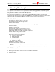
VIO-Velocity - Operating Manual Rev 09/09. Elmo Motion Control Introduction This manual is intended for the use of the design engineer who is implementing the VIO-Velocity servo amplifier into a machine. It covers the various aspects of the implementation process from basic understanding of the product concept and features, through a detailed explanation of the user accessible functions, down to mounting guidelines and requirements from peripheral devices.
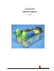
VIO-Velocity - Operating Manual Rev 09/09. Elmo Motion Control Servo Amplifier Description The VIO-Velocity extends the VIO line by adding a velocity loop daughter board. This series of miniature servo amplifiers for DC brush motors incorporate custom mixed analog/digital ICs and hybridized power stage. The product meets UL508c and the suitable CE regulations. The power stage is implemented on a single ceramic substrate.
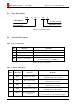
Elmo Motion Control 2.3 Rev 09/09 VIO-Velocity - Operating Manual Type Designation VIO 15 / 55 V VIO amplifier Velocity version Rated current Maximum voltage Figure 1: Type Designation 2.4 Terminal Description 2.4.1 Power connections. Pin VP+ Function Positive power Input PR Power input Return M1 Motor power output 1 M2 Motor power output 2 Remarks Voltage determined by VIO model This output will be positive when pin CREF (+) is positive relatively to pin CREF (-).
VIO-Velocity - Operating Manual Rev 09/09. Elmo Motion Control Pin # Short form Function Remarks 6 ECLP External current limit – peak External voltage reduces the Ip limit. For more details see "current limit paragraph". 7 ECLRET Current limits return Return for the current limit signals.
Elmo Motion Control 2.5 Rev 09/09 VIO-Velocity - Operating Manual DIP Switches Switch Function Armature Feedback signal. ON Armature Feedback is connected. OFF Armature Feedback is disconnected. CFM Changing S2 to ON position multiplies the current feedback signal by 2. CFM – OFF S3 CGC Changing S3 to ON position reduces the proportional gain (P) of the current loop by 70%. CGC – OFF S4 LM Latch mode. Non-Latch mode.
VIO-Velocity - Operating Manual 2.6 Rev 09/09. Elmo Motion Control Test Points Test point Function Description VM Velocity Feedback signal ±4V CC Current Command to the VIO ±3.75V = nominal Ip of the VIO GND Ground GND Ground G G Table 4: Test Points 2.7 Adjustable Components. Potentiometer Function Description Adjust for 4V on VM at max velocity. P1 Velocity Feedback gain. P2 Offset trimmer. With command at 0V adjust to cancel drift.
Elmo Motion Control Rev 09/09 VIO-Velocity - Operating Manual Component R1 Stock Value Not installed Function Tachometer feedback resistor. (See 3.4 below) R2 Not installed Tachometer feedback resistor. (See 3.4 below) R3 Not installed Tachometer feedback resistor. (See 3.4 below) R4 Not installed I x R compensation resistor. (See 3.9.2 below) R5 24.3KΩ Input scaling resistor. (See 3.1 below) R6 24.3KΩ Input scaling resistor. (See 3.
VIO-Velocity - Operating Manual Rev 09/09.
VIO-Velocity - Operating Manual Rev 09/09. Elmo Motion Control Operation of the Servo Control 3.1 Command The user can change the default scale of the differential input (±10.0V) by calculating and inserting R5 & R6 into the designated solderless terminals. The value of theses resistors is given by: R5 = R 6 = 2.5 *VIN ( MAX ) = Kohms The factory default values of R5 and R6 are 25Kohms. This value is for ±10V command input.
Elmo Motion Control 3.3 Rev 09/09 VIO-Velocity - Operating Manual Current Gain Control (CGC) The amplifier is equipped with Current Gain Control (CGC) for improved performance of low induction motors. By switching S3 to the ON position the gain of the current loop is reduced, thus enabling the use of low inductance motors without the insertion of an additional inductor. The default (S3 OFF) is high gain. Switching S3 to the ON position reduces the proportional gain (P) of the current loop by approx.
VIO-Velocity - Operating Manual 3.5.1 Rev 09/09. Elmo Motion Control ECLP external voltage An external positive voltage (0 to 3.75V) to terminal ECLP in reference to terminal ECLRET will control peak current limit from zero to Ip (nom). IP ( new ) = VECLP * IP ( nom ) 3.75V Remarks: The voltage will be internally clamped to 3.75V whenever the external VECLP will be higher than 3.75V. The external voltage source must be capable to source/ sink at least ±0.2 ma. The max absolute VECLP is 12V.
Elmo Motion Control 3.8 Rev 09/09 VIO-Velocity - Operating Manual Limit switches When one direction of rotation is disabled, the reference input is clamped to 0V in this direction. Please be aware that the unit can still drift due to offset. If an absolute stop is critical to the application the controller of the machine should also handle the switch. 3.8.1 FLS To enable the operation of the amplifier in the forward direction the FLS opto must be “on”. This can be done by either of two methods: 1.
VIO-Velocity - Operating Manual 3.9.1 Rev 09/09. Elmo Motion Control Tachometer feedback When using Tachometer feedback the user must select the scale for the differential input by calculating and inserting R1 & R2 into the designated solderless terminals. The value of theses resistors is given by: R1 = R 2 = 2.5 *VTM = Kohms VTM = maximum Tachometer voltage at the differential Input.
Elmo Motion Control Rev 09/09 VIO-Velocity - Operating Manual 3.10 Response Adjustment (Velocity Mode Only) In most applications optimum response is achieved by adjusting the compensation (COMP) trimmer. Adjustment procedure is as follows: - Provide the amplifier with a low frequency, bi-directional square wave velocity command (A 0.5Hz, ±2V waveform is often employed).
VIO-Velocity - Operating Manual Rev 09/09.
Elmo Motion Control Rev 09/09 VIO-Velocity - Operating Manual 3.11 Current Mode In order to operate the servo amplifier as a current amplifier, the velocity loop should be disabled. This is done by converting the error amplifier into a low gain DC amplifier that has a flat response beyond the desired current bandwidth.
VIO-Velocity - Operating Manual Rev 09/09. Elmo Motion Control Mounting and wiring instructions 4.1 Heat Sink Mounting The VIO series dissipates its heat by natural convection for loads up to 500W. For higher output loads the amplifier should be mounted on an additional heat sink or cooled by fan. Care should be taken that the motor leads are as short as possible. The capacitance of long shielded motor leads can cause the amplifier to generate a significant amount of heat. There are two 4.
Elmo Motion Control Rev 09/09 VIO-Velocity - Operating Manual Guidelines for connecting a non isolated amplifier with an isolating power transformer Ground: DC power common Motor chassis Amplifier's heat sink 4.3 DC power supply DC power supply can be at any voltage in the range defined within the technical specifications.
VIO-Velocity - Operating Manual Rev 09/09.
VIO-Velocity - Operating Manual Rev 09/09.
Elmo Motion Control Rev 09/09 VIO-Velocity - Operating Manual Table 13: Environmental specification Parameter Operating ambient temperature Max. Case temperature Storage temperature Operating humidity Max. Operating altitude Storage humidity Protective coating Value 0-60°C (32-140°F) 87°C (-2°C/+7°C) (188.6°F (-3.6°F/+12.
VIO-Velocity - Operating Manual Rev 09/09.
VIO-Velocity - Operating Manual Rev 09/09. Elmo Motion Control Accessories 8.1 Interface & Evaluations Boards Elmo offers an interface connection board, the SIB-SSA, to simplify the connection of the VIO-Velocity for prototyping and evaluation. The SIB-SSA connects with a ribbon cable to signal connector J4 and provides those signals to the user on a convenient terminal strip.
VIO-Velocity - Operating Manual Rev 09/09. Elmo Motion Control Service Centers and Warranty ISRAEL Elmo Motion Control LTD 64 Gisin ST. Petah-Tikva 49103 Tel: (03)922-0864 Fax: (03)922-6949 EUROPE Switzerland Elmo Motion Control 7 Stanserstrasse CH-6362 Stansstad Tel: +41 41 6100775 Fax: +41 41 6100778 Germany Elmo Motion Control GmbH Steinbeisstrasse 41 D-78056 Villingen-Schwenningen Tel: +49 7720 857760 Fax: +49 7720 857770 U.S.A Elmo Motion Control Inc.