Piccolo Analog Servo Drive Installation Guide July 2014 (Ver. 2.301) www.elmomc.
Notice This guide is delivered subject to the following conditions and restrictions: • This guide contains proprietary information belonging to Elmo Motion Control Ltd. Such information is supplied solely for the purpose of assisting users of the Piccolo servo drive in its installation. • The text and graphics included in this manual are for the purpose of illustration and reference only. The specifications on which they are based are subject to change without notice.
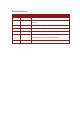
Revision History Version Date Details Ver. 1.0 May 1999 Initial release Ver. 2.0 May 2003 Manual name revised to Piccolo User Guide and look updated Ver. 2.1 Aug 2004 50 VDC models upgraded to 60 VDC models Ver. 2.2 Apr 2008 Updated Power Ratings Table in Appendix Ver. 2.201 Feb 2013 Updated Section 3.3: Piccolo Dimensions Ver. 2.300 Apr 2013 Formatted according to the new template Updated Section 5.2: Electrical Specifications Ver. 2.
Elmo Worldwide Head Office Elmo Motion Control Ltd. 60 Amal St., P.O. Box 3078, Petach Tikva 49516 Israel Tel: +972 (3) 929-2300 • Fax: +972 (3) 929-2322 • info-il@elmomc.com North America Elmo Motion Control Inc. 42 Technology Way, Nashua, NH 03060 USA Tel: +1 (603) 821-9979 • Fax: +1 (603) 821-9943 • info-us@elmomc.com Europe Elmo Motion Control GmbH Hermann-Schwer-Strasse 3, 78048 VS-Villingen Germany Tel: +49 (0) 7721-944 7120 • Fax: +49 (0) 7721-944 7130 • info-de@elmomc.
Piccolo Installation Guide MAN-PICIG (Ver. 2.301) Table of Contents Chapter 1: 1.1. 1.2. 1.3. 1.4. 1.5. Warnings......................................................................................................................... 8 Cautions .......................................................................................................................... 8 Directives and Standards ................................................................................................
Piccolo Installation Guide Table of Contents MAN-PICIG (Ver. 2.301) 4.6. 4.7. 4.8. 4.9. Latch Mode (LM) .......................................................................................................... 26 “30/60” Hall Sensor Selector (SEL) ............................................................................... 26 Amplifier Enable Logic .................................................................................................. 26 Status Indications ................................
Piccolo Installation Guide 7 MAN-PICIG (Ver. 2.301) Chapter 1: Safety I nform ation In order to operate the Piccolo servo drive safely, it is imperative that you implement the safety procedures included in this installation guide. This information is provided to protect you and to keep your work area safe when operating the Piccolo and accompanying equipment. Please read this chapter carefully, before you begin the installation process.
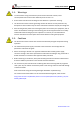
Piccolo Installation Guide Safety Information MAN-PICIG (Ver. 2.301) 1.1. Warnings • To avoid electric arcing and hazards to personnel and electrical contacts, never connect/disconnect the servo drive while the power source is on. • Disconnect the Piccolo from all voltage sources before it is opened for servicing. • The Piccolo servo drive contains grounding conduits for electric current protection. Any disruption to these conduits may cause the instrument to become hot (live) and dangerous.
Safety Information Piccolo Installation Guide MAN-PICIG (Ver. 2.301) 1.3.
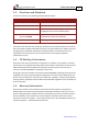
Piccolo Installation Guide 10 MAN-PICIG (Ver. 2.301) Chapter 2: Product Description This installation guide describes the Piccolo servo drive and the steps for its wiring, installation and power-up. Following these guidelines ensures optimal performance of the drive and the system to which it is connected. 2.1. Drive Description The Piccolo series of miniature servo amplifiers is designed for DC brushless motors and incorporates custom mixed analog/digital ICs and a hybrid power stage.
Piccolo Installation Guide Product Description MAN-PICIG (Ver. 2.301) 2.3. Fault Protection The Piccolo includes built-in protection against possible fault conditions, including: • Shorts between the outputs or between each output and the power input/return • Over-temperature • Under/over voltage • Failure of internal power supplies • Latch mode for each protective feature www.elmomc.
Product Description Piccolo Installation Guide MAN-PICIG (Ver. 2.301) 2.4. System Architecture 10.5K 10nF 100K 10K 44.2K 20K 20K - 20K + 20K ECLC(J1,3) 1K ECLP(J1,4) 1K - A + CFM(J1,10) Current Feedback Processor Current Limits CL return(J1,5) CM(J1,6) Buffer 27.4K CREF+ (J1,1) AS Current Loop Amp. AD CGC(J1,8) 14.
Piccolo Installation Guide Product Description MAN-PICIG (Ver. 2.301) 2.5. How to Use this Guide In order to install and operate the Piccolo servo drive, you will use this manual in conjunction with a set of Elmo documentation.
Piccolo Installation Guide 14 MAN-PICIG (Ver. 2.301) Chapter 3: I nstallation 3.1. Site Requirements You can guarantee the safe operation of the Piccolo by ensuring that it is installed in an appropriate environment. Feature Value Ambient operating temperature 0 °C – 50 °C (32 °F – 122 °F) Maximum case temperature 87 °C (188 °F) Note: Models for extended environmental conditions are available. 3.2.
Installation Piccolo Installation Guide MAN-PICIG (Ver. 2.301) 3.3. Dimensions Figure 2: Piccolo Dimensions www.elmomc.
Installation Piccolo Installation Guide MAN-PICIG (Ver. 2.301) 3.4. Mounting the Piccolo 3.4.1. Mounting the Heatsink The Piccolo dissipates its heat by natural convection, up to loads of 500 W. For higher output loads, the amplifier should be mounted on an additional heatsink or cooled by fan. There are two 4.5-mm holes in the base plate for mounting an additional heatsink, see Figure 2. 3.4.2.
Piccolo Installation Guide Installation MAN-PICIG (Ver. 2.301) 3.5. Wiring the Piccolo Figure 3: Piccolo Basic Wiring www.elmomc.
Installation Piccolo Installation Guide MAN-PICIG (Ver. 2.301) 3.6. 3.6.1. Connections Pin Functions The Piccolo connections are described in the following figure and tables. Figure 4 Piccolo Connector Locations 3.6.1.1. Power Pin Function Remarks VP+ Positive power input PR Power input return M1 Motor power output 1 M2 Motor power output 2 M3 Motor power output 3 Table 3: Piccolo Power Connections www.elmomc.
Installation Piccolo Installation Guide MAN-PICIG (Ver. 2.301) 3.6.1.2. J1 Connector Pin #/ Function Short Form Remarks 1 Positive input of a differential amplifier: Current command input ( + ) CREF1+ 2 Current command input ( - ) CREF3 External current limit - peak ECLP 5 Input operating voltage range: ±3.75 V • Maximum input voltage: ±20 V, see Section 4.
Installation Piccolo Installation Guide MAN-PICIG (Ver. 2.301) 3.6.1.3. J2 Connector Pin #/ Function Short Form Remarks 1 SEL Hall sensor selector Input for selection of Hall signal format. The default (open pin) is 60°. When shorting this pin to pin J2/2 (LM), the selected Hall format is changed to 30°. 2 Latch mode Latch mode input. Return for Latch mode (LM). LMRET Latch mode return 4 Enable ( + ) Positive voltage input of "Amplifier Enable” function.
Installation Piccolo Installation Guide MAN-PICIG (Ver. 2.301) 3.6.1.4. J3 Connector Pin #/ Function Short Form Remarks 1 +5V +5 V Hall/encoder supply voltage +5 V supply voltage for Hall sensors. Output current: 20 mA. 2 Hall A input Logic levels: TTL Maximum input voltage: 30 VDC. Return used only for Hall supply. HARET Hall/encoder supply voltage return 4 Hall B input Logic levels: TTL Ha 3 Hb Maximum input voltage 30 VDC.
Installation Piccolo Installation Guide MAN-PICIG (Ver. 2.301) 3.7. DC Power Supply The DC power supply can be at any voltage in the range defined in Chapter 5: Technical Specifications. The supply source must comply with the safety aspects of the relevant requirements, in accordance with the most recent version of the standard EN60950 or equivalent Low Voltage Directive Standard, all according to the applicable over-voltage category.
Servo Control Operation Piccolo Installation Guide MAN-PICIG (Ver. 2.301) Chapter 4: Servo Control Operation 4.1. Current Command Input The Piccolo has a single differential input. The input operating voltage range is ± 3.75 V, meaning that a 3.75 V signal will result in a fully rated peak current. The current limit circuits will override this signal if the peak duration exceeds 2.7 seconds and/or the required current exceeds the values set by the ECLC and ECLP signals.
Piccolo Installation Guide Servo Control Operation MAN-PICIG (Ver. 2.301) 4.3. Current Gain Control (CGC) The Piccolo amplifier is equipped with Current Gain Control (CGC) for improved performance of low induction motors. Connecting pin J1/8 to J1/9 reduces the gain of the current loop, thus enabling the use of low inductance motors without the insertion of an additional inductor. The default (pin J1/8 left open) is high gain.
Servo Control Operation Piccolo Installation Guide MAN-PICIG (Ver. 2.301) 4.4. External Current Limit - Continuous (ECLC) The continuous current limit of the Piccolo amplifier can be scaled down by an external voltage or by an external resistor connected from pin J1/3 (ECLC) to pin J1/5 (ECLRET). 4.4.1. External Voltage An external positive voltage (0 to 3.75 V) to terminal J1/3 (ECLC) in reference to terminal J1/5 (ECLRET) will control the continuous current limit from zero to Ic(nom).
Servo Control Operation Piccolo Installation Guide MAN-PICIG (Ver. 2.301) 4.5.2. External Resistor Connect an external resistor between terminal J2/3 (ECLP) and terminal J2/2 (ECLRET). The resistor value is given by:: RECLP (Kohm) = 37.4 * Ip(new) Ip(nom) -1 • 0 < RECLP < 36.4 K (1/8 Watt) • At RECLP greater than 36.4 K, the current limit will be internally clamped to the nominal value. • IP(nom) is the nominal peak current limit of the amplifier. 4.6.
Servo Control Operation Piccolo Installation Guide MAN-PICIG (Ver. 2.301) 4.9. 27 Status Indications The following table lists the Piccolo amplifier status indications.
Technical Specifications Piccolo Installation Guide MAN-PICIG (Ver. 2.301) Chapter 5: Technical Specifications 15/200 10/200 6/200 2/200 20/100 15/100 10/100 3/100 25/60 Units 15/60 Feature 10/60 Power Ratings 5/60 5.1.
Technical Specifications Piccolo Installation Guide MAN-PICIG (Ver. 2.301) 5.2. Electrical Specifications Feature Details Switching frequency on the load 34 kHz (±10%) Current loop bandwidth Up to 4 kHz Current step response < 100 μsec Peak current duration (full rated peak current) Utilization dependent up to 2.7 sec ±15%, reduced by RMS current limit Offset current at normal room temperature 25°C (±1.
Technical Specifications Piccolo Installation Guide MAN-PICIG (Ver. 2.301) 5.4.
Technical Specifications Piccolo Installation Guide MAN-PICIG (Ver. 2.301) 5.5. Compliance with Standards Specification Details Quality Assurance ISO 9001:2008 Quality Management Design Approved IEC/EN 61800-5-1, Safety Printed wiring for electronic equipment (clearance, creepage, spacing, conductors sizing, etc.) MIL-HDBK- 217F Reliability prediction of electronic equipment (rating, de-rating, stress, etc.
Technical Specifications Piccolo Installation Guide MAN-PICIG (Ver. 2.