Ocarina/Castanet Analog Servo Drives Installation Guide February 2009 - Ver. 1.4 www.elmomc.
Notice This guide is delivered subject to the following conditions and restrictions: This guide contains proprietary information belonging to Elmo Motion Control Ltd. Such information is supplied solely for the purpose of assisting users of the Ocarina and Castanet servo drives in their installation. The text and graphics included in this manual are for the purpose of illustration and reference only. The specifications on which they are based are subject to change without notice.
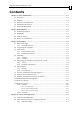
Ocarina/Castanet Installation Guide MAN-OCSIG (Ver. 1.4) Contents Chapter 1: Safety Information............................................................................................... 1-1 1.1 Warnings.................................................................................................................... 1-2 1.2 Cautions..................................................................................................................... 1-2 1.3 Directives and Standards ....................
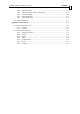
Ocarina/Castanet Installation Guide Contents MAN-OCSIG (Ver. 1.4) 4.2.2 4.2.3 4.2.4 4.2.5 4.2.6 External Resistor................................................................................................4-2 External Current Limit - Peak (ECLP) ............................................................4-2 External Voltage ................................................................................................4-2 External Resistor............................................................
Ocarina/Castanet Installation Guide MAN-OCSIG (Ver. 1.4) Chapter 1: Safety Information In order to achieve the optimum, safe operation of the Ocarina and Castanet servoamplifiers, it is imperative that you implement the safety procedures included in this installation guide. This information is provided to protect you and to keep your work area safe when operating the Ocarina and Castanet and accompanying equipment. Please read this chapter carefully before you begin the installation process.
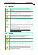
Ocarina/Castanet Installation Guide Safety Information MAN-OCSIG (Ver. 1.4) 1.1 Warnings To avoid electric arcing and hazards to personnel and electrical contacts, never connect/disconnect the servo drive while the power source is on. Power cables can carry a high voltage, even when the motor is not in motion. Disconnect the Ocarina and Castanet from all voltage sources before they are opened for servicing.
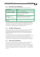
Ocarina/Castanet Installation Guide Safety Information MAN-OCSIG (Ver. 1.4) 1.
Ocarina/Castanet Installation Guide MAN-OCSIG (Ver. 1.4) Chapter 2: Introduction This Installation Guide is intended for design engineers who are integrating an Elmo Motion Control Ocarina and Castanet servo amplifiers into a machine. 2.1 Product Description The Ocarina and Castanet series of servo-amplifiers was designed to deliver “the highest possible power density”. The Ocarina can deliver up to 1.4 kW of continuous power or 2.8 kW of peak power in a matchbox size (2.25 in³ or 38cc) package.
Ocarina/Castanet Installation Guide Introduction MAN-OCSIG (Ver. 1.4) 2.3 Fault Protection Built-in protection against possible fault conditions, including: • Shorts between the outputs or between each output and the power input/return • Over-heating • Under/over voltage • Failure of internal power supplies • Latch mode for each protective feature 2.4 How to Use this Guide Installation is the first step in integrating and operating the Elmo Ocarina and Castanet servo amplifiers.
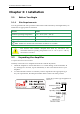
Ocarina/Castanet Installation Guide 3-1 31 MAN-OCSIG (Ver. 1.4) Chapter 3: Installation 3.1 Before You Begin 3.1.1 Site Requirements You can guarantee the safe operation of the Ocarina and Castanet by ensuring that they are installed in an appropriate environment.
Ocarina/Castanet Installation Guide Installation MAN-OCSIG (Ver. 1.4) 3. Verify that the Ocarina or Castanet type is the one that you ordered, and ensure that the voltage meets your specific requirements. 3.3 3.3.1 Dimensions Ocarina Dimensions Figure 3-1: Ocarina Dimensions 3.3.
Ocarina/Castanet Installation Guide Installation MAN-OCSIG (Ver. 1.4) 3.4 Mounting 3.4.1 Ocarina The Ocarina was designed for mounting on a printed circuit board (PCB). It is connected by 2 mm pitch 0.51 mm square pins. When designing the Ocarina into a device, be sure to leave about 1 cm (0.4") outward from the heatsink to enable free air convection around the Ocarina. We recommend that the Ocarina be soldered directly to the board.
Ocarina/Castanet Installation Guide Installation MAN-OCSIG (Ver. 1.4) 3.5 Integrating the Ocarina and Castanet on a PCB The Ocarina and Castanet are designed to be mounted on a PCB, either by soldering its pins directly to the PCB or by using suitable socket connectors. In both cases the following rules apply: 3.5.1 Traces 1. The size of the traces on the PCB (thickness and width) is determined by the current carrying capacity required by the application.
Ocarina/Castanet Installation Guide Installation MAN-OCSIG (Ver. 1.4) 3. Main Power Supply and Motor Traces: The power traces must be kept as far away as possible from the feedback and control traces. 4. PE Terminal: The PE terminal is connected directly to the Ocarina's heatsink or to the Castanet's two PE strips on its lower board. In the Ocarina, the heatsink serves as an EMI common plane. The PE terminal should be connected to the system's Protective Earth.
Ocarina/Castanet Installation Guide Installation MAN-OCSIG (Ver. 1.4) 3.6.2 Pin # 3-6 Connector J1 Short Form Function Description 1 EN+ Enable + Positive voltage input of the “Amplifier Enable” function. To enable operation of the amplifier, the optocoupler must be energized by applying voltage between this pin (+) and pin J1/22 (-). The optocoupler is isolated from the amplifier. See Figure 3-4. “OFF” voltage: 0 V < Vin < 1 V. “ON” voltage: 2.
Ocarina/Castanet Installation Guide Installation MAN-OCSIG (Ver. 1.4) Pin # Short Form Function Description 14 ECLP External current limit peak External voltage scales down the rated value. Voltage range: 0 V to 3.75 V (3.75 V = rated Ip) Refer to Section 4.2. 15 LMRET Return for Latch Mode signals.
Ocarina/Castanet Installation Guide MAN-OCSIG (Ver. 1.4) 3.
Ocarina/Castanet Installation Guide Installation MAN-OCSIG (Ver. 1.4) 3.8 Pin 3-9 Main Power and Motor Power Function Cable Pin Positions VP+ Pos. Power input Power PR Power return Power PE Protective earth Power AC Motor DC Motor PE Protective earth Motor Motor M1 Motor phase Motor N/C M2 Motor phase Motor Motor M3 Motor phase Motor Motor When connecting several amplifiers to several motors, all should be wired in the same motor phases and feedback sequences.
Ocarina/Castanet Installation Guide Installation MAN-OCSIG (Ver. 1.4) 3.11 DC Power Supply The DC power supply can be at any voltage in the range defined in the technical specifications (the Appendix of this guide). The supply source must comply with the safety aspects of the relevant requirements, in accordance with the most recent version of the standard EN60950 or equivalent Low Voltage Directive Standard, all according to the applicable over-voltage category.
Ocarina/Castanet Installation Guide MAN-OCSIG (Ver. 1.
Ocarina/Castanet Installation Guide Installation MAN-OCSIG (Ver. 1.4) 3.12 Heat Dissipation 3.12.1 Ocarina 3-12 The best way to dissipate heat from the Ocarina is to mount it so that its heatsink faces up. For best results leave approximately 10 mm of space between the Ocarina's heatsink and any other assembly. 3.12.1.1 Thermal Data • • • Heat dissipation capability (θ): Approximately 10 °C/W.
Ocarina/Castanet Installation Guide Installation MAN-OCSIG (Ver. 1.4) 3-13 Whistle-100 100 Series Power Dissipation Ocarina Power Dissipation (W) 6.0 5.0 External heat sink required Standard 40 °C Ambient Temp. 4.0 Heatsink not required 3.0 2.0 1.0 5 4. 5 4 3. 5 3 2. 5 2 1. 5 1 0. 5 0 0.0 Peak Current (A) 85VDC 70VDC 50VDC 3.12.1.3 How to Use the Charts The charts above are based upon theoretical worst-case conditions. Actual test results show 30% - 50% better power dissipation.
Ocarina/Castanet Installation Guide MAN-OCSIG (Ver. 1.4) Chapter 4: Servo Control Operation 4.1 Current Command Input The Ocarina and Castanet have a single differential input. The input operating voltage range is ± 3.75 V, meaning that a 3.75 V signal will result in a fully rated peak current. The current limit circuits will override this signal if the peak duration exceeds 2.7 seconds and/or the required current exceeds the values set by the ECLC and ECLP signals.
Ocarina/Castanet Installation Guide Servo Control Operation MAN-OCSIG (Ver. 1.4) 4.2.2 External Resistor RECLC (Kohm) = 37.4 * Ic(new) Ic(nom) -1 Connect an external resistor between terminal J1/9 (ECLC) and terminal J1/8 (ECLRET). The resistor value is given by: 0 < RECLC < 36.4 K (1/8 Watt) At RECLC greater than 36.4 K, the current limit will be internally clamped to the nominal value. IC(nom) is the nominal continuous current limit of the amplifier. 4.2.
Ocarina/Castanet Installation Guide Servo Control Operation MAN-OCSIG (Ver. 1.4) 4.2.5 External Resistor RECLP (Kohm) = 37.4 * Ip(new) Ip(nom) -1 Connect an external resistor between terminal J1/14 (ECLP) and terminal J1/8 (ECLRET). The resistor value is given by: 0 < RECLP < 36.4 K (1/8 Watt) At RECLP greater than 36.4 K, the current limit will be internally clamped to the nominal value. IP(nom) is the nominal peak current limit of the amplifier. 4.2.
Ocarina/Castanet Installation Guide Servo Control Operation MAN-OCSIG (Ver. 1.4) Notes: Without latch mode: The status indications are reset when the fault disappears. With latch mode: The Short, Over Temperature and Commutation Failure status indications are reset when the enable signal is temporarily removed from the enable input. Multiple faults: Only the reading of the first fault is reliable. Additional faults add on to the status outputs and the indication is therefore meaningless.
Ocarina/Castanet Installation Guide A-1 MAN-OCSIG (Ver. 1.4) Appendix: Specifications A.1 General Specifications A.1.1 Ocarina Feature Units 1/60 2.5/60 Minimum supply voltage VDC 11 20 Nominal supply voltage VDC 50 85 Maximum supply voltage VDC 59 95 Maximum continuous power output W Efficiency at rated power (at nominal conditions) % 55 140 5/60 280 10/60 15/60 1/100 2.5/100 5/100 10/100 15/100 570 850 90 230 460 A Peak current limit A 2 x Ic g (oz) 45 g (1.
Ocarina/Castanet Installation Guide Specifications MAN-OCSIG (Ver. 1.4) A.1.2 Castanet Feature Units 3/60 2.5/100 Minimum supply voltage VDC 11 20 Nominal supply voltage VDC 50 85 Maximum supply voltage VDC 59 95 Maximum continuous power output W 190 240 Efficiency at rated power % Maximum output voltage Up to 99% 93% of DC bus voltage at f=32 kHz DC and trapezoidal commutation continuous current limit (Ic) A Peak current limit A 2 x Ic g (oz) 21.5 g (0.
Ocarina/Castanet Installation Guide Specifications MAN-OCSIG (Ver. 1.4) A.2 Standards Compliance A.2.1 Quality Assurance Specification Details ISO 9001:2000 Quality Management A.2.2 A-3 Design Specification Details MIL-HDBK- 217F Reliability prediction of electronic equipment (rating, de-rating, stress, etc.) IPC-D-275 Printed wiring for electronic equipment (clearance, creepage, spacing, conductors sizing, etc.) IPC-SM-782 IPC-CM-770 UL508c UL840 In compliance with IEC68 A.2.
Ocarina/Castanet Installation Guide Specifications MAN-OCSIG (Ver. 1.4) A.2.4 EMC Specification Details In compliance with Electromagnetic compatibility (EMC) EN55011 Class A with EN61000-6-2: Immunity for industrial environment, according to: IEC61000-4-2 / criteria B IEC61000-4-3 / criteria A IEC61000-4-4 / criteria B IEC61000-4-5 / criteria B IEC61000-4-6 / criteria A IEC61000-4-8 / criteria A IEC61000-4-11 / criteria B/C A.2.