Ocarina Evaluation Board User Guide October 2008 (Ver. 2.
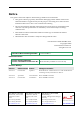
Notice This guide is delivered subject to the following conditions and restrictions: This guide contains proprietary information belonging to Elmo Motion Control Ltd. Such information is supplied solely for the purpose of assisting users of the Ocarina Evaluation Board servo drive in its evaluation and testing. The text and graphics included in this manual are for the purpose of illustration and reference only. The specifications on which they are based are subject to change without notice.
Ocarina Evaluation Board User Guide MAN-EVLBRD-OCA (Ver. 2.1) Contents Chapter 1: Safety Information ...........................................................................................1-1 1.1 Warnings ............................................................................................................1-2 1.2 Cautions..............................................................................................................1-2 1.3 Directives and Standards...............................
Ocarina Evaluation Board User Guide Contents MAN-EVLBRD-OCA (Ver. 2.1) Appendix: Cables ...............................................................................................................A-1 A.1 Cable Photos .................................................................................................... A-1 A.2 Cable Kits ......................................................................................................... A-2 A.3 Logic Cable (CBL-DAUX-1) ..............................
Ocarina Evaluation Board User Guide MAN-EVLBRD-OCA (Ver. 2.1) Chapter 1: Safety Information In order to achieve the optimum, safe operation of the Ocarina Evaluation Board, it is imperative that you implement the safety procedures included in this installation guide. This information is provided to protect you and to keep your work area safe when operating the Ocarina Evaluation Board and accompanying equipment. Please read this chapter carefully before you begin the installation process.
Ocarina Evaluation Board User Guide Safety Information MAN-EVLBRD-OCA (Ver. 2.1) 1.1 Warnings To avoid electric arcing and hazards to personnel and electrical contacts, never connect/disconnect the servo drive while the power source is on. Power cables can carry a high voltage, even when the motor is not in motion. Disconnect the Ocarina Evaluation Board from all voltage sources before it is opened for servicing. The Ocarina Evaluation Board contains grounding conduits for electric current protection.
Ocarina Evaluation Board User Guide Safety Information MAN-EVLBRD-OCA (Ver. 2.1) 1.
Ocarina Evaluation Board User Guide Safety Information MAN-EVLBRD-OCA (Ver. 2.1) 1.6 Before You Begin 1.6.1 Site Requirements 1-4 You can guarantee the safe operation of the Ocarina Evaluation Board by ensuring that it operates in an appropriate environment.
Ocarina Evaluation Board User Guide 2-1 MAN-EVLBRD-OCA (Ver. 2.2) Chapter 2: Evaluation Board Connectors and Cables The Ocarina Evaluation Board was designed to help when evaluating the Ocarina Analog Servo Drive. It comes with standard terminal blocks for power connections and D-sub plugs/sockets for signals connections. It also comes with a complete set of cables for connecting to the board. 2.
Ocarina Evaluation Board User Guide Evaluation Board Connectors and Cables 2-2 MAN-EVLBRD-OCA (Ver. 2.2) 2.2 Evaluation Board-Connector Cross-Reference Table Catalog No.
Ocarina Evaluation Board User Guide Evaluation Board Connectors and Cables MAN-EVLBRD-OCA (Ver. 2.2) 2.
Ocarina Evaluation Board User Guide Evaluation Board Connectors and Cables MAN-EVLBRD-OCA (Ver. 2.2) 2.4 2-4 Ocarina Connections on Evaluation Board The Ocarina is connected to the Evaluation Board by 2mm pitch header connectors. Upon assembly, the Ocarina's J1 and Power pins should be pressed directly into their respective sockets. Great care should be taken with alignment to avoid bending the pins. No. Pins 2x11 Type 2 mm Pitch 0.
Ocarina Evaluation Board User Guide Evaluation Board Connectors and Cables MAN-EVLBRD-OCA (Ver. 2.2) 2.4.
Ocarina Evaluation Board User Guide Evaluation Board Connectors and Cables MAN-EVLBRD-OCA (Ver. 2.2) 2.4.2 2-6 Connecting the Ocarina to the Evaluation Board Each Ocarina has 35 pins, therefore, great care should be taken aligning its pins with the sockets on the board when assembling. Push the Ocarina into the Evaluation Board firmly and evenly. M2.5X5mm Spring washers 4 spacers recommended M2.
Ocarina Evaluation Board User Guide Evaluation Board Connectors and Cables MAN-EVLBRD-OCA (Ver. 2.2) 2.5 The Main Power and Motor Power Connector Pin Function Cable VP+ Pos.
Ocarina Evaluation Board User Guide Evaluation Board Connectors and Cables MAN-EVLBRD-OCA (Ver. 2.2) 2.5.2 2-8 Connecting Main Power Connect the main power supply cable to the VP+ and PR terminals of the main power connector. Notes for connecting the DC power supply: The source of the 0 ~ 95 VDC Main Power Supply must be isolated. For best immunity, it is highly recommended to use twisted and shielded cables for the DC power supply cable. A 3-wire shielded cable should be used.
Ocarina Evaluation Board User Guide Evaluation Board Connectors and Cables MAN-EVLBRD-OCA (Ver. 2.2) 2.7 Auxiliary Supply (optional) Notes for 12 ~ 95 VDC Auxiliary Supply connections: The source of the 12 ~ 95 VDC Auxiliary Supply must be isolated from the main. For safety reasons, connect the return (common) of the Auxiliary Supply source to the closest ground near the Auxiliary Supply source. Connect the cable shield to the closest ground near the Auxiliary Supply source.
Ocarina Evaluation Board User Guide Evaluation Board Connectors and Cables MAN-EVLBRD-OCA (Ver. 2.2) 2.8 2-10 Halls Connector P1 Pin Signal Function Pin Positions 1 HA Hall A input 2 HC Hall C input 3 HALL+5V +5V Hall supply voltage 4 HARET Hall supply voltage return 5 HARET Hall supply voltage return 6 HB Hall B input 7 N.C N.C 8 N.C N.C 9 N.C N.
Ocarina Evaluation Board User Guide Evaluation Board Connectors and Cables MAN-EVLBRD-OCA (Ver. 2.2) 2.9 2-11 Logic Connector P2 Current command scaling resistors (R8 and R9 of the orcad design) The user can change the default scale of the differential input (±3.75) by calculating and inserting R8 and R9 into the designated solderless terminals. The value of these resistors are given by: R8=R9=5.33XVcref-20 Vcref is the desired maximum reference voltage.
Ocarina Evaluation Board User Guide Evaluation Board Connectors and Cables MAN-EVLBRD-OCA (Ver. 2.2) 2.10 Status OK Connector P3 Pin Function Remarks 1 AOK Refer to section 3.6.2 in the “Ocarina Installation Guide” 2 SO1 Refer to section 3.6.2 in the “Ocarina Installation Guide” 3 SO2 Refer to section 3.6.2 in the “Ocarina Installation Guide” 4 +VCC Through this interface, the user can activate and use the “on-board” LED-Display, by applying a power source between P3/4 and P3/6.
Ocarina Evaluation Board User Guide Evaluation Board Connectors and Cables MAN-EVLBRD-OCA (Ver. 2.2) 2.
Ocarina Evaluation Board User Guide Evaluation Board Connectors and Cables MAN-EVLBRD-OCA (Ver. 2.2) 2.13 2-14 Powering Up After the Ocarina is mounted on the Ocarina Evaluation Board and the cables have been connected to their devices, the Ocarina Evaluation Board is ready to be powered up. Caution: Before applying power, ensure that the DC supply is within the specified range and that the proper plus-minus connections are in order. 2.
Ocarina Evaluation Board User Guide A-1 MAN-EVLBRD-OCA (Ver. 2.1) Appendix: Cables A.1 Cable Photos Logic Cable: Status OK Cable: Motor Power Cable: CBL-DAUX-1 CBL-D003-1 Halls Cable: CBL-MTRPWR3-1 Aux.
Ocarina Evaluation Board User Guide Cables MAN-EVLBRD-OCA (Ver. 2.1) A.2 Cable Kits A full set of cables is supplied with the Evaluation Board. The cables are all 1m in length. Each set contains the cables listed below. Additional cable kits and individual cables (individually or in multiples of 10 each) are available from Elmo. Cable Application Cable Part. No.
Ocarina Evaluation Board User Guide Cables MAN-EVLBRD-OCA (Ver. 2.1) A.3 A-3 Logic Cable (CBL-DAUX-1) The Logic cable (CBL-DAUX-1) is made of 24-AWG shielded cable with a 15-pin D-sub socket. It connects to the LOGIC port on the Evaluation Board. It is open on the motor side so that it can be connected to customer-specific connectors. Pin No.
Ocarina Evaluation Board User Guide Cables MAN-EVLBRD-OCA (Ver. 2.1) A.4 Halls Cable (CBL-A001-1) CBL-A001-1 is a 24-AWG shielded cable with a 9-pin D-sub plug. It can be connected to the Evaluation Board's Halls FEEDBACK port. The Halls are used to transfer feedback data from the motor to the drive Pin Color 1 2 3 4 5 6 7 8 9 Brown White Yellow Red Blue Pink N.C N.C N.C Pair Pin Position pair pair CEL0040A-DWG COR016A 9 Pin D-Sub Plug Figure A-2: Halls Cable (Part No.
Ocarina Evaluation Board User Guide Cables MAN-EVLBRD-OCA (Ver. 2.1) A.5 Status OK (CBL-D003-1) The Status OK cable is a 24-AWG shielded cable. It is connected using a 9-pin D-sub socket. Pin Color 1 Brown 6 2 White Yellow 3 Green 4 5 7 8 9 Red N.C N.C N.C Pink Pair Pin Position pair pair 9 Pin D-Sub Socket Figure A-3: Status OK Cable (Part No.
Ocarina Evaluation Board User Guide Cables MAN-EVLBRD-OCA (Ver. 2.1) A.6 A-6 Motor Power Cables (CBL-MTRPWR3-1) CBL-MTRPWR3-1 is a general-purpose motor power cable. It is made from 24-AWG shielded wires with pin terminals on the Evaluation Board end. The pins are ought to be connected to the Phoenix plug supplied with the board. The other end is open so that it can be attached to a customer-specific connector.
Ocarina Evaluation Board User Guide Cables MAN-EVLBRD-OCA (Ver. 2.1) A.8 A-7 Guidelines for Making Your Own Cables Proper wiring, grounding and shielding are essential for ensuring safe, immune and optimal servo performance of the Ocarina Evaluation Board. If you do not plan to use cables provided by Elmo, follow the instructions below carefully. Follow these instructions to ensure safe and proper wiring: Use twisted pair shielded cables for control, feedback and communication connections.
Ocarina Evaluation Board User Guide Cables MAN-EVLBRD-OCA (Ver. 2.1) A.8.1 Recommended Wire Cross Sections Function Connection Details Motor PE, M1, M2, M3 24 AWG Auxiliary power VL, PR 24 AWG Feedback and Control HALLS 24 AWG twisted pair shielded cables as described below (Section A.8.4) LOGIC STATUS OK A.8.2 A-8 Feedback and Control Cable Assemblies The Ocarina Evaluation Board features easy-to-use D-sub type connections for all Control and Feedback cables.
Ocarina Evaluation Board User Guide Cables MAN-EVLBRD-OCA (Ver. 2.1) A.8.3 A-9 Recommended Wire Cross Sections Function Connection Details Motor PE, M1, M2, M3 24 AWG Auxiliary power VL, PR 24 AWG Feedback and Control MAIN FEEDBACK 24 AWG twisted pair shielded cables as described below (Section A.8.4) AUX FEEDBACK GENERAL I/O MAIN BUFFERED OUTPUT Communications RS-232 CANopen A.8.4 26 AWG twisted pair shielded cables as described below (Section A.8.