Maestro Installation Guide September 2008 (Ver. 1.33) www.elmomc.
Important Notice This guide is delivered subject to the following conditions and restrictions: This guide contains proprietary information belonging to Elmo Motion Control Ltd. Such information is supplied solely for the purpose of assisting users of Maestro motion controller. The text and graphics included in this manual are for the purpose of illustration and reference only. The specifications on which they are based are subject to change without notice.
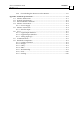
Maestro Installation Guide MAN-MASIG (Ver. 1.33) Contents Chapter 1: Safety Information .................................................................................................... 1-1 1.1 Cautions................................................................................................................ 1-2 1.2 Directives and Standards.................................................................................... 1-2 1.3 Warranty Information ...............................................
Maestro Installation Guide Contents MAN-MASIG (Ver. 1.33) 4.6.6 Downloading the Resources to the Maestro............................................. 4-11 Appendix: Technical Specifications ......................................................................................... A-1 A.1 Maestro Dimensions.......................................................................................... A-1 A.2 General Specifications ...............................................................................
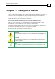
Maestro Installation Guide MAN-MASIG (Ver 1.33) Chapter 1: Safety Information In order to achieve the optimum, safe operation of the Maestro Multi-Axis Supervisor, it is imperative that you implement the safety procedures included in this installation guide. This information is provided to protect you and to keep your work area safe when operating the Maestro and accompanying equipment. Please read this chapter carefully before you begin the installation process.
Maestro Installation Guide Safety Information MAN-MASIG (Ver 1.33) 1.1 Cautions The Maestro must be connected to an approved 24VDC power supply through a line that is separated from hazardous line voltages using reinforced or double insulation in accordance with approved safety standards. Before switching on the Maestro, verify that all safety precautions have been observed and that the installation procedures in this manual have been followed. 1.
Maestro Installation Guide MAN-MASIG (Ver 1.33) Chapter 2: Introduction This installation guide describes the Maestro Multi-Axis Supervisor and the steps for its wiring, installation and powering up. Following these guidelines ensures maximum functionality of the system to which it is connected. 2.1 Description Elmo’s Maestro is a network-based multi-axis motion supervisor that operates in conjunction with Elmo intelligent servo drives to provide a full multi-axis motion control solution.
Maestro Installation Guide Introduction MAN-MASIG (Ver 1.33) 2.
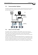
Maestro Installation Guide Introduction MAN-MASIG (Ver 1.33) 2.3 Communication Options The Maestro communicates with the PC through a standard RS-232 connection, through a TCP/IP network or with a direct Ethernet cable connection. It communicates with the drives by CANopen protocol. Setup Ethernet Multi Axis Motion Control RS-232 CANopen Single Axis Motion Control 2.
Maestro Installation Guide Introduction MAN-MASIG (Ver 1.
Maestro Installation Guide 3-1 MAN-MASIG (Ver 1.33) Chapter 3: Installation 3.1 Before You Begin 3.1.1 Site Requirements You can guarantee the safe operation of the Maestro by ensuring that it is installed in an appropriate environment. Feature Value Ambient operating temperature 0° to 40°C (32° to 113°F) Maximum relative humidity 90% non-condensing Operating area atmosphere No flammable gases or vapors permitted in area 3.1.
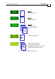
Maestro Installation Guide Installation MAN-MASIG (Ver 1.33) 3.1.3 Hardware Requirements The components that you will need to install your Maestro are: Connector Described in Section 24v 3.6 24v 3.6 ETHERNET 3.4.2 CANopen Communication cable(s) CAN1 CAN2 3.4.3 RS-232 Communications Cable (if needed) RS-232 3.5.
Maestro Installation Guide Installation MAN-MASIG (Ver 1.33) Component Digital I/O Cable Analog Input Encoder Connector DIGITAL I/O Described in Section Diagram 3.5.2 ANALOG INPUT 3.5.3 ENCODER 3.5.
Maestro Installation Guide Installation MAN-MASIG (Ver 1.33) 3.2 3-4 Unpacking the Components Before you begin working with the Maestro system, verify that you have all of its components, as follows: The Maestro Multi-Axis Supervisor Maestro software which may be downloaded from www.elmomc.com The Maestro is shipped in a cardboard box with styrofoam protection. To unpack the Maestro: 1. Carefully remove the Maestro from the box. 2.
Maestro Installation Guide Installation MAN-MASIG (Ver 1.33) 3.3 Mounting the Maestro The Maestro has been designed for "in-back" mounting: “Wall Mount” – screwed onto a panel M4 round head screws, one through each opening in the heat sink, are used to mount the Maestro (see the diagram below) on a wall.
Maestro Installation Guide Installation MAN-MASIG (Ver 1.33) 3.4 3-6 Connecting the Cables 3.4.1 Wiring the Maestro Once the Maestro is mounted, you are ready to wire the device. Proper wiring, grounding and shielding are essential for ensuring safe, immune and optimal servo performance of the Maestro. Follow these instructions to ensure safe and proper wiring: Use twisted pair shielded cables for communication connections.
Maestro Installation Guide Installation MAN-MASIG (Ver 1.33) Type Function Port 9-pin D-Sub M Comm. RS-232 8-pin RJ-45 Ethernet ETHERNET Mini Circular 6-Pin DIN Reserved 15-pin D-Sub (high-density) Reserved Connector Location Ethernet Comm.
Maestro Installation Guide Installation MAN-MASIG (Ver 1.33) 3.4.2 3-8 Ethernet Notes for connecting the Ethernet communication cable: Use a shielded Cat 5 FTP Ethernet cable. One of two types of Ethernet cables may be needed depending on your setup: • standard cable (used for connecting the Maestro to a PC through a hub, switch or router) • cross cable (used for connecting a PC to the Maestro) Std. Eth. Cable Eth.
Maestro Installation Guide Installation MAN-MASIG (Ver 1.33) 3.4.3 3-9 CANopen Communication Notes for connecting the CANopen communication cable: Use 26 or 28 AWG twisted pair shielded cables. For best results, the shield should have aluminum foil and covered by copper braid with a drain wire (CAT5 FTP applicable). Connect the shield to the ground of the host (PC). Usually, this connection is soldered internally inside the connector at the PC end.
Maestro Installation Guide Installation MAN-MASIG (Ver 1.33) 3.5 3-10 D-sub Cable Assemblies The Maestro features easy-to-use D-sub type connections for various cables. These cables are available from Elmo. The instructions and diagrams below are designed to help customers who wish to build their own cables. Use 24, 26 or 28 AWG twisted-pair shielded cables (24 AWG cable is recommended). For best results, the shield should have aluminum foil covered by copper braid.
Maestro Installation Guide Installation MAN-MASIG (Ver 1.33) 3.5.1 3-11 RS-232 Communication (if needed) Notes for connecting the RS-232 communication cable: Use of a standard, commercial CAT-5 null-modem cable may be acceptable for most applications. However, Elmo recommends using a 26 to 28 AWG, twisted pair cable shielded by aluminum foil and copper braid with drain wire. Elmo recommends that both female connectors have a metal cover.
Maestro Installation Guide Installation MAN-MASIG (Ver 1.33) 3.5.2 3-12 Digital I/O Port The Digital I/O port has a 26-pin high density D-Sub socket. When assembling this I/O cable, follow the instructions in Section 3.5 (D-sub Cable Assemblies) using a 26-pin high density metal case D-sub female connector (socket).
Maestro Installation Guide Installation MAN-MASIG (Ver 1.33) 3.5.3 Analog Input Port The Analog Input port has a 15-pin high density D-Sub socket. When assembling this I/O cable, follow the instructions in Section 3.5 (D-sub Cable Assemblies) using a 15-pin high density metal case D-sub male connector (plug).
Maestro Installation Guide Installation MAN-MASIG (Ver 1.33) 3.5.4 3-14 Encoder Port The Incremental Encoder port has a 9-pin density D-Sub socket. When assembling this encoder cable, follow the instructions in Section 3.5 (D-sub Cable Assemblies) using a 9-pin high density metal case D-sub male connector (plug). Pin Signal 1 A+ 2 A- 3 B+ 4 B- 5 IN+ 6 GROUND 7 +5v 8 RET GRD 9 IN- Function Pin Position CEL0040A-DWG COR016A Table 3-10: Encoder Cable - Pin Assignments 3.
Maestro Installation Guide Installation MAN-MASIG (Ver 1.33) 3-15 Maestro Power Supply Figure 3-7: Power Supply (24v) Connection Diagram 3.7 Powering Up After the Maestro has been mounted, check that the cables are intact. The Maestro is then ready to be powered up. 3.8 Initializing the System After the Maestro has been connected and mounted, the system must be set up and initialized.
Maestro Installation Guide MAN-MASIG (Ver 1.33) Chapter 4: Maestro Software Setup 4.1 Maestro Software Installation Maestro software is "shrink-wrapped" with Elmo Composer software. Consequently, the first part of the Maestro's software setup is the installation of Elmo's Composer You can install the Composer either by using the CD-ROM delivered with the Elmo servo drive or by downloading the software directly from the Elmo website. 4.1.
Maestro Installation Guide Maestro Software Setup MAN-MASIG (Ver 1.33) 9. Click Next and follow the instructions to install the Composer. The Choose Destination dialog opens which enables you to pick a directory for the Composer. The default is C:\Program Files\ELMO Motion Control\Composer. 10. Upon completion of the installation, you may wish to create a desktop shortcut for fast access to the application. 11. Confirm that the installation worked by selecting Start menu/Programs/Elmo. 12.
Maestro Installation Guide Maestro Software Setup MAN-MASIG (Ver 1.33) 4.2 Running the Composer with the Maestro Select Start/Programs/Elmo/Composer to start Elmo's Composer and check the setup. 1. In the Welcome menu select the Open Communication Directly option. 2. In the Application Name and Communication Type dialog box check the TCP/IP Gateway option and click the Properties button. 3. In the Select Drive dialog you should see at least one Maestro in the Gateway list. Select it. 4.
Maestro Installation Guide Maestro Software Setup MAN-MASIG (Ver 1.33) 4.3 4-4 Configuring the Maestro Maestro can be connected in two ways: Through a Network (with a DHCP server) Peer-to-Peer Std. Eth. Cable Eth. Cro ss Cable Ethernet Hub/Switch/Router Figure 4-1 Maestro Connected to a Network 4.3.1 Figure 4-2 Maestro Connected Peer-to-Peer to PC DHCP Connection When the Maestro is connecting to a network with a DHCP server, its IP address is provided automatically.
Maestro Installation Guide Maestro Software Setup MAN-MASIG (Ver 1.33) 4.4 Telnet Terminal Communications When there are several Maestros connected to the LAN it’s a good idea to give each a unique name. This is done through a Telnet connection as follows: 1. Select Start/Run in Windows. 2. Type Telnet and the I.P. address in the Open dialog. 3. Type name to see the current name of the Maestro at that address. 4. Type name followed by your name of choice. 5.
Maestro Installation Guide Maestro Software Setup MAN-MASIG (Ver 1.33) 4.4.1 Peer-to-Peer Connection When connecting a Maestro directly to a PC, select Start/Settings/Control Panel to open the Control Panel and then select Network and Dial-up Connections/Local Area Connection/Properties to set the IP address of the Maestro manually. In the Internet Protocol Properties menu select the Use the following IP address option and enter 10.0.0.2 for the IP address and 255.0.0.0 for the Subnet mask.
Maestro Installation Guide Maestro Software Setup MAN-MASIG (Ver 1.33) 4.5 Checking the Resources on the CAN Buses Once you have established communications with the Maestro you can use the Elmo Studio to check what devices are connected. This is done by opening the Resource View, selecting a CAN Bus, clicking the right mouse button and selecting Update CAN Bus Info.
Maestro Installation Guide Maestro Software Setup MAN-MASIG (Ver 1.33) 4.6 4-8 Setting up the Resources Once the Maestro knows what devices are on the CAN bus, you can set them up. The first step is to name the resources. 4.6.1 Axes The axes are set up as follows: 1. Select a CAN bus. 5. Select a Node ID. 2. Click the right mouse button. 6. Give the node a name (such as Axis_1 or a1) 3. Select Insert. 7. Select a Type (Elmo or DS402). 4. Select Axis. 8. Click OK 9.
Maestro Installation Guide Maestro Software Setup MAN-MASIG (Ver 1.33) 4.6.3 4-9 Groups The groups are set up as follows: 1. Select a CAN bus. 5. Select Group ID. 2. Click the right mouse button. 6. Give the group a name (such as Group). 3. Select Insert. 7. Select a Type (Elmo or DS402). 4. Select Group. 8. From the list on the left-hand side, select the object name and add or delete them using the arrow-buttons. 9. Click OK. 10. Repeat for each of the other axes. 4.6.
Maestro Installation Guide Maestro Software Setup MAN-MASIG (Ver 1.33) 4-10 1. Select a CAN bus. 5. Select Node ID. 2. Click the right mouse button. 6. Give the IO a name (such as IO) 3. Select Insert. 7. Select a Type (DS401). 4. Select IO. 8. Select the I/O Sub Type (DIN for input and DOUT for output devices). 9. Click OK. 10. Repeat for each of the other CAN input devices.
Maestro Installation Guide Maestro Software Setup MAN-MASIG (Ver 1.33) 4.6.6 Downloading the Resources to the Maestro When all the resources have been set up, they must be downloaded to the Maestro. The setup is downloaded by clicking the right mouse button and selecting Download Resources.
Maestro Installation Guide MAN-MASIG (Ver 1.33) Appendix: Technical Specifications A.
Maestro Installation Guide Technical Specifications MAN-MASIG (Ver 1.33) A-2 A.2 General Specifications Weight 350 grams (12.3 ounces) Dimensions 105 x 44 X 76 mm (4.1” x1.7” x 3.0”) Mounting Method (with adapter) Wall Mount (“Bookshelf”) Digital In / Digital Out / Analog In 8/8/4 A.
Maestro Installation Guide Technical Specifications MAN-MASIG (Ver 1.33) Pins Type Port 9 D-Sub M RS-232 8 RJ-45 ETHERNET 6 Mini DIN Circular Reserved 15 D-Sub (high-density) Reserved Connector Location Ethernet Comm.
Maestro Installation Guide Technical Specifications MAN-MASIG (Ver 1.33) A.4.1 Power Supply Feature Details Auxiliary power supply DC source only Auxiliary supply input voltage 24 V +20% Auxiliary supply input power 30 W A.5 Maestro Connectors A.5.
Maestro Installation Guide Technical Specifications MAN-MASIG (Ver 1.33) A-5 A.6 I/O’s The Bassoon has: A.6.
Maestro Installation Guide Technical Specifications MAN-MASIG (Ver 1.33) A.6.
Maestro Installation Guide Technical Specifications MAN-MASIG (Ver 1.33) A.6.3 Analog Input (J7) Feature Details Maximum operating differential mode voltage 15 V Maximum absolute differential input voltage 20 V Differential input resistance Analog input command resolution 3.
Maestro Installation Guide Technical Specifications MAN-MASIG (Ver 1.33) A.7 Communications Specification Details Ethernet 0ne 10/100 Base-T Ethernet RS-232 Signals: RxD , TxD , Gnd Baud Rate of 9,600 ~ 115,200 bits/sec. CANopen CANbus Signals: CAN_H, CAN_L, CAN_GND Maximum Baud Rate of 1 Mbits/sec. Version: DS 301 V4.
Maestro Installation Guide Technical Specifications MAN-MASIG (Ver 1.33) A.8 A-9 Standards Compliance A.8.1 Quality Assurance Specification Details ISO 9001:2000 Quality Management A.8.2 Design Specification Details MIL-HDBK- 217F Reliability prediction of electronic equipment (rating, de-rating, stress, etc.) IPC-D-275 IPC-SM-782 IPC-CM-770 Printed wiring for electronic equipment (clearance, creepage, spacing, conductors sizing, etc.) UL508c UL840 In compliance with IEC68 A.
Maestro Installation Guide Technical Specifications MAN-MASIG (Ver 1.33) A.8.6 PCB Specification Details In compliance with IPC-A-600, level 2 Acceptability of printed circuit boards A.8.