Motion Control Library Tutorial January 2007 (Ver. 1.
Notice This tutorial is delivered subject to the following conditions and restrictions: This tutorial contains proprietary information belonging to Elmo Motion Control Ltd. The text and graphics included in this manual are for the purpose of illustration and reference only. The specifications on which they are based are subject to change without notice. Elmo Motion Control and the Elmo Motion Control logo are trademarks of Elmo Motion Control Ltd.
Motion Library Tutorial MAN-MLT (Ver 2.0) Contents Chapter 1: General Description .............................................................................................. 1 1.1 Introduction ............................................................................................................ 1 1.2 Vector properties ...................................................................................................... 1 1.3 Trajectory generation ...................................................
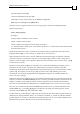
Maestro Motion Library Tutorial MAN-INTUG (Ver. 1.7) Chapter 1: General Description 1.1 Introduction The Motion Library (ML) produces trajectories based on the PVT mechanism. It implements a set of functions that calculate trajectories as PVT tables for the vector motion. As a result of a call to the Motion Library functions, the user gets a PVT table for the requested trajectory. It supports two and three-dimensional vector motion. A PVT table is a two or three-dimensional sequence of PVT points.
Maestro Motion Library Tutorial 2 MAN-INTUG (Ver. 1.7) general trajectory time (vtt) switch arc definitions (vsc, vsr, vsd) admissible velocity and position errors definitions (vpe,vve) PVT step low and high limits (VNT,VXT ) All of the vector’s properties can be set in a user program or by the Command Interpreter. Syntax of a property: Vector_name.property Examples: v1.vsp - defines maximum vector velocity v1.vtt - defines trajectory time v1.
Maestro Motion Library Tutorial MAN-INTUG (Ver. 1.7) 1.3 Trajectory generation 1.3.1 Line Target position for a line is defined by the parameters of the function line(): Two-dimensional line V1.line(x,y) – produces a line trajectory from the current position to the point (x,y), where x and y integer values in counts. Three-dimensional line V1.line(x,y,z) – produces line trajectory from the current position to the point (x,y,z), where x,y and z - integer values in counts. 1.3.
Maestro Motion Library Tutorial 4 MAN-INTUG (Ver. 1.7) Other popular types of splines like Bezier curves, B- splines or NURBS are usually not interpolation but smoothing splines. The spline curve does not move through the given points but near them.
Maestro Motion Library Tutorial 5 MAN-INTUG (Ver. 1.7) 1.3.3.1 Examples for the two-dimensional spline interpolation Example Example (Motion Mathematic Lib Samples\ Vector_2D \ Spline_Ellipse – www.elmomc.com) Ellipse trajectory (2D spline interpolation) v1.vum=1 //build trajectory in max velocity mode v1.vac = 28000000 //max acceleration v1.vdc = 28000000 //max deceleration v1.vsp = 50000 v1.vse = 0 //max. velocity //end velocity pi = 3.
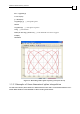
Maestro Motion Library Tutorial MAN-INTUG (Ver. 1.7) for t = 0:pi/72:2*pi x = R*cos(3*t) y = R*sin(5*t) v1.splinep(x,y) // add spline point end for v1.splinee(0) // end spline sequence v1.bg //start motion while (a1.ms==2)||(a2.ms==2) //wait until both axes have stopped wait(10) end while Figure 1-1: Recording of the spline trajectory (Lissajous curves) 1.3.3.
Maestro Motion Library Tutorial MAN-INTUG (Ver. 1.7) Figure 1-2: Resources for the 3D vector Example (Motion Mathematic Lib Samples\ Vector_3D \ Spline_3D – www.elmomc.com) A spline curve throws a number of arbitrary points SetAxisStartPos(a1, 0) //set coordinate x to 0 SetAxisStartPos(a2, 0) //set coordinate y to 0 SetAxisStartPos(a3, 0) //set coordinate y to 0 v2.vsp = 50000 v2.vse=0 v2.splines() // start spline sequence v2.splinep(0, 0, 0) // add spline 3D point v2.
Maestro Motion Library Tutorial 8 MAN-INTUG (Ver. 1.7) For this operator to work properly, the first line of the PVT table containing a text header must be removed.
Maestro Motion Library Tutorial MAN-INTUG (Ver. 1.7) Figure 1-5: Projection on the XZ plane Example (Motion Mathematic Lib Samples\ Vector_3D \ Helix – www.elmomc.com) Helix curve built with the use of the spline interpolation. SetAxisStartPos(a1, 50000) //set coordinate x to 0 SetAxisStartPos(a2, 0) //set coordinate y to 0 SetAxisStartPos(a3, 0) //set coordinate y to 0 v2.vsp = 50000 v2.
Maestro Motion Library Tutorial MAN-INTUG (Ver. 1.7) Yc = Y - R*sin(Teta) // X coordinate of the helix axis v2.splines() // start spline sequence for i=0:1:n v2.splinep(X,Y,Z) // add spline 3D point Teta = Teta + dTeta // calc teta for the next point X = Xc + R*cos(Teta) // calc X coordinate for the next point Y = Yc + R*sin(Teta) // calc Y coordinate for the next point Z = Z + dZ // calc Z coordinate for the next point end for v2.splinee(0) // end spline sequence v2.
Maestro Motion Library Tutorial MAN-INTUG (Ver. 1.7) Inside the polyline operator parenthesis vector_name.starts(trj_name) and vector_name.ends() can be added function calls – addline(), addcircle(), addsplinep() and adddwell() to define polyline segments. For the 2D polyline vector_name.addline (int PosX, int PosY) – adds a line segment PosX, PosY - destination position of the linear segment (counts) vector_name.
Maestro Motion Library Tutorial 12 MAN-INTUG (Ver. 1.7) 3. vsc = 2 – ML builds switch arc with the switch radius vsr (this parameter must be set by the user). 4. vsc = 3 - ML builds a switch arc with the switch radius implicitly pre-defined via parameter vsd (distance along the line from the intersection point). Parameter vsd must be set by the user. For vsc = 2 and vsc = 3, the user can check if the values of the parameters vsr and vsd satisfy geometric constraints.
Maestro Motion Library Tutorial 13 MAN-INTUG (Ver. 1.7) Figure 1-7: Recording of the polyline trajectory Any trajectory generated by the Motion Library (single shape or polyline) can be rotated relative to init point due to vector property vra – rotation angle in degrees. Example (Motion Mathematic Lib Samples\ Vector_2D \ LineCircleRotated – www.elmomc.com) // The same polyline rotated at –90 degrees relative to init point v1.vac = 28000000 v1.vdc = 28000000 v1.vum = 1 v1.
Maestro Motion Library Tutorial 14 MAN-INTUG (Ver. 1.7) Figure 1-8: Recording of the rotated polyline 1.3.4.2 Examples for the three-dimensional polyline Example (Motion Mathematic Lib Samples\ Vector_3D \ Rectangle – www.elmomc.com) Three-dimensional rectangle SetAxisStartPos(a1, 0) //set coordinate x to 0 SetAxisStartPos(a2, 0) //set coordinate y to 0 SetAxisStartPos(a3, 0) //set coordinate y to 0 v2.vsc=2 v2.vsr=12000 v2.vsp = 70000 //max. vector velocity v2.vse = 70000 v2.starts() v2.
Maestro Motion Library Tutorial 15 MAN-INTUG (Ver. 1.
Maestro Motion Library Tutorial 16 MAN-INTUG (Ver. 1.7) Figure 1-11: Projection on the YZ plane 1.4 Transition to a new trajectory with a non-zero velocity If a transition from one trajectory to another (for instance from a line to a circle) must be executed with a velocity not equal to zero at the switch point, the Motion Library builds a switch curve to achieve smooth modification of the velocity. Such a curve is implemented as a circle arc.
Maestro Motion Library Tutorial 17 MAN-INTUG (Ver. 1.7) In fact, the value defined as the calculations. 2. r ≥ (vse) 2/(vae*vac ) (by default vae = 0.9) must be used in Implicitly pre-defined by the user via smooth distance d along the line from the intersection point (vsc = 3, vsd defined). This mode can be implemented to the line – line, circle – line and line – circle trajectory intersections. 3.
Maestro Motion Library Tutorial 18 MAN-INTUG (Ver. 1.7) Input parameters and intersection geometry define the influence of a switch arc on a trajectory. The main cases of shapes intersection are considered below. Here as an example to consider two lines intersection. If an angle between two lines is small, even a switch arc with a small radius can significantly change initial trajectory while an arc with the same radius can be insignificant for lines o with intersection angle close to 180 .
Motion Library Tutorial Switch Radius Calculation MAN-MLT (Ver 2.0) Chapter 2: Switch Radius Calculation 2.1 Line – line intersection If a trajectory contains a switch from line L1 to line L2 with non-zero velocity, the direction of the vector velocity cannot be changed at the one intersection point. To implement such a switch, insert into a trajectory an additional element – circle arc is inserted into a trajectory (see-Figure 2-1). The switch arc radius must satisfy (1-1).
Motion Library Tutorial Switch Radius Calculation MAN-MLT (Ver 2.0) vsr ≤ min(0.5ΔL1, 0.5ΔL2)*tg(γ/2) (2.1-4) and kinematics constraint Vend ≤ [r*vae*ACv)]1/2 (2.1-5) where vae – acceleration error (default value – 0.9). So the user defined parameters must satisfy vse ≤ [vsr*vae*vac]1/2 (2.1-6) vse – segment end velocity, vsr – switch radius, vac – vector acceleration. Example 2.1a Line 1 is defined by its init point (50000, 70000) and end point (60000,20000). .
Motion Library Tutorial Switch Radius Calculation MAN-MLT (Ver 2.0) r_max = dmax*tg(γ/2) = 50000* tg(0.5*0.1974) = 4951 This value is limiting and produces singular trajectory with the switch arc that replaces L2. So we should take some value less than limiting value 4951 for instance 0.5* r_max = 0.5*4951 = 2475. Now we can recalculate maximum end velocity (vse) that satisfies this value: vse = [r*vac*vae]1/2 = [2475*500000*0.
Motion Library Tutorial Switch Radius Calculation MAN-MLT (Ver 2.0) vse = [r_switch*vac*vae]1/2 = [4455.9*500000*0.9]1/2 = 44778.9 Example 2.1c (Motion Mathematic Lib Samples \Line To Line\LineLineMinRad_Ex_2c www.elmomc.com) Line 1 is defined by its init point (300000, 900000) and end point (700000,200000). Line 2 is defined by the init point (700000,200000) and its end point (1100000,700000). Switch from Line 1 to Line 2 must be executed with the minimal switch radius (vsc = 1).
Motion Library Tutorial Switch Radius Calculation MAN-MLT (Ver 2.0) Line 1 is defined by its init point (300000, 900000) and end point (700000,200000). Line 2 is defined by the init point (700000,200000) and its end point (1100000,700000). Switch from Line 1 to Line 2 must be executed with a distance from the intersection point pre-defined by the user vsc = 3, vsd = 20000. We define cruise velocity vsp = 50000 and end velocity vse = 50000. Vector acceleration/deceleration vac = vdc = 28000000 1.
Motion Library Tutorial Switch Radius Calculation MAN-MLT (Ver 2.0) 2-6 2.2 Circle – line intersection Note: C – circle arc, L – line, R – circle radius, r – switch arc radius, (Xc,Yc) - circle center, (Xi, Yi) – intersection point, (Xlast, Ylast) – last point on the circle (Xfirst, Yfirst) – first point on the line L, d – distance from point (Xi, Yi) to point (Xfirst, Yfirst), (Xo,Yo) – switch arc center coordinates.
Motion Library Tutorial Switch Radius Calculation MAN-MLT (Ver 2.0) Figure 2-2 Example 2-2 (Motion Mathematic Lib Samples\Circle to Line\ Section 2_2_1_1\ CircleLine_Ex_2_2 – www.elmomc.com) Circle arc is defined by its init position Xfrom = 0, Yfrom = 100000, radius R = 100000, init angle α = 90o(with axis X positive direction), and sweep angle = 180o. Line end point Xto = -140000, Yto = 100000.
Motion Library Tutorial Switch Radius Calculation MAN-MLT (Ver 2.0) Yp = Yc + K*(Xp – Xc) = 0 +0.7*(-46979 - 0) = -32885 And the perpendicular length h = [(Xc – Xp)2 + (Yc - Yp)2]1/2 = [(0 + 46979)2 + (0 + 32885)2]1/2 = 57345 Max switch radius calculated by (2.2.1.1-1) Rmax = (R – h)/2 = (100000 – 57345)/2 = 21328 Rmin = 1000002/(2800000*0.9) = 396.8 As a switch radius we can take any value Rswitch that satisfies Rmin < Rswitch < Rmax We take Rswitch = (Rmin + Rmax)/2 = (21328 + 396.
Motion Library Tutorial Switch Radius Calculation MAN-MLT (Ver 2.0) The length of the perpendicular h should also be calculated. By knowing the line equation in a form Ax + By + C = 0 (2.2.1.1-3) then h can be calculated by h = |AXc + BYc + C|/(A2 + B2)1/2 (2.2.1.1-4) If line L is defined by its starting point (X1,Y1) and end point (X2,Y2), coefficients A,B,C can be calculated by formulas in Appendix 2 or Appendix 1. To define r we can use an equation (R – r)2 = (h + r)2 + u2 (2.2.1.
Motion Library Tutorial Switch Radius Calculation MAN-MLT (Ver 2.0) Figure 2-4 In our calculations was not taken in account additional requirement that the switch arc should not take more than 50% of the segment length. So the calculated switch arc with the radius 22917 takes the whole line segment. If in the calculations, some point on the line is used, for example (65000, 50000), instead of the line end point, then u = 65000 and the result is: r = 0.
Motion Library Tutorial Switch Radius Calculation MAN-MLT (Ver 2.0) r = ρ1ρ2/(ρ1 + ρ2) (2.2.1.1-10) As in the previous case, the user defined parameter vsr must obey (vse)2/vac < vsr < ρ1ρ2/(ρ1 + ρ2) (2.2.1.1-11) Figure 2-5 Example 2-6 (Motion Mathematic Lib Samples\Circle to Line\ Section 2_2_1_1\ CircleLine_Ex_2_6 – www.elmomc.com) The circle arc in Figure 2-6 is defined by the radius R = 100000, init angle α = -90o, sweep angle β = 30o and the init position Xfrom = 0, Yfrom = -100000.
Motion Library Tutorial Switch Radius Calculation MAN-MLT (Ver 2.0) ρ1= 100000 - |C/B| = 100000 - |(-3464101600.0)/(-90000)| = 61509.98222 r = ρ1ρ2/(ρ1 + ρ2) = 61509.98*44322.66/(61509.98 + 44322.66)= 25760.351 meaning that the switch radius in use must be less than this limiting value. Figure 2-6 Values calculated by (2.2.1.1-7) and (2.2.1.1-10) are not recommended but limiting values. The switch radius in use must be less those values. Such limiting values produce irregular cases of intersection.
Motion Library Tutorial Switch Radius Calculation MAN-MLT (Ver 2.0) Figure 2-7 This condition is not always sufficient. Adequacy depends on arc and line lengths. If the ∈ circle’s center projection on the line L belongs to the line segment (P1 L) and an intersection point of the continued perpendicular with the circle arc belonging to the circle segment P2 ∈ C then (2.2.1.2-1) is sufficient.
Motion Library Tutorial Switch Radius Calculation MAN-MLT (Ver 2.0) Figure 2-8 Example 2-9 (Motion Mathematic Lib Samples\Circle to Line\ Section 2_2_1_2\ CircleLine_Ex_2_9 – www.elmomc.com) The circle arc (Figure 2-9) is defined by its radius R = 100000, init angle α angle β = 0o and sweep = -45o, init point P1(100000, 0). Line target position (-40000, 0). In this case ρ1 = 40000, ρ2 = 140000 - line (P1,P3) coincide with axis X.
Motion Library Tutorial Switch Radius Calculation MAN-MLT (Ver 2.0) Figure 2-9 Projection of the circle arc init point P1 on the line L does not belong to the line segment L. If a projection of the circle arc init point P1 on the line L does not belong to the line segment L (Figure 2-10), calculate the maximum switch radius r using equation ρ2(Oc,P5) + (r – h)2 = (R – r)2 (2.2.1.2-4) or (ρ1)2 + (r – h)2 = (R – r)2 (2.2.1.2-5) (ρ1)2 + r2 – 2rh + h2 = R2 – 2Rr + r2 (2.2.1.
Motion Library Tutorial Switch Radius Calculation MAN-MLT (Ver 2.0) Figure 2-10 Example 2-11 (Motion Mathematic Lib Samples\Circle to Line\ Section 2_2_1_2\ CircleLine_Ex_2_11 – www.elmomc.com) Circle arc (Figure 2-11) is defined by its init position (X = 0, Y = 60000), radius R = 60000, init angle α = 0o, and a sweep angle β = -135o. Line target position 25000, -42426. Circle center coordinates (Xc, Yc) = (0 – Rcos90, 60000 – Rsin90) = (0,0).
Motion Library Tutorial Switch Radius Calculation MAN-MLT (Ver 2.0) 2.2.1.3 Line intersects the center of the circle Consider the last case of the circle – line intersection: the line goes inside the circle through the center of the circle (Figure 2-12-2-15). The following cases are possible: a) The length of the line ΔL is greater than the circle radius R and the circle diameter ∈ orthogonal to the line intersects the circle arc: P1 C1 (Figure 2-12).
Motion Library Tutorial Switch Radius Calculation MAN-MLT (Ver 2.0) Figure 2-13 Example 2-14 (Motion Mathematic Lib Samples\Circle to Line\ Section 2_2_1_3\ CircleLine_Ex_2_14 – www.elmomc.com) The circle C1 (Figure 2-14) is defined by its init point (80000,0), radius R = 80000, init angle α = 0 and a sweep angle β = -135. Line target position (-28284, -28284). The length 1/2 of the line segment ΔL = 28284*2 = 40000.
Motion Library Tutorial Switch Radius Calculation MAN-MLT (Ver 2.0) c) The circle arc sweeps an angle less than 90o and a perpendicular dropped from the circle init point P1 on the line L intersects line segment at point P 2 15). A projection of the circle init point P1(X1,Y1) on the line L ∈ C1 (Figure 2- – point P2(X2,Y2) and the length of the segment defined by the line init point P3 and projection point P2: ρ1 = ρ(P3,P2) can be determined.
Motion Library Tutorial Switch Radius Calculation MAN-MLT (Ver 2.0) By (a1.6) we have Xp = (Yo – Y1 + kX1 – qXo)/(k – q) = (–80000 + 56569 – 56569 - 0)/(1+1) = – 40000 Yp = Yo + q(X – Xo) Distance ρ1 = = -80000 – (–40000 - 0) = –40000. ρ(P3,P2) = [(–40000 + 56569)2 + (–40000 + 56569)2]1/2 = 23432 For the maximum switch radius we get from (3.1.3-5) r = [2Rρ1 – (ρ1)2]/(2R) = [2*80000*23432 - 234322]/160000 = 20000 Figure 2-16 2.2.
Motion Library Tutorial Switch Radius Calculation MAN-MLT (Ver 2.0) ρ[(Xp,Yp),(X1,Y1)] = r (2.2.2.1.1-2) The following is known: ρ3 = ρ[(Xp,Yp),(Xf, Yf)] = ρ[(Xp,Yp),(Xi, Yi)] + d (2.2.2.1.1-3) where (Xi, Yi) – circle-line intersection point . As ρ[(X1,Y1),(Xo, Yo)] = ρ[(Xp,Yp),(Xf, Yf)] = ρ3 then use an equation to define r (R + r)2 – (ρ3)2 = (ρ1 – r)2 (2.2.2.1.1-4) From (2.2.2.1.1-4) for r there is r = [(ρ3)2 + (ρ1)2 – R2]/(2R + 2ρ1) (2.2.2.1.1-5) 2.2.2.1.
Motion Library Tutorial Switch Radius Calculation MAN-MLT (Ver 2.0) Figure 2-18 so an equation can be written (R – r)2 – (ρ1 – r)2 = (ρ3)2 (2.2.2.1.2-2) that produces for r r = [R2 – (ρ3)2 – (ρ1)2]/(2R – 2ρ1) (2.2.2.1.2-3) 2.2.2.2 Initial circle center and switch arc center belong to two half planes defined by the line L. 2.2.2.2.1 Line continues outside the circle (Figure 2-19) In this case ρ3 = ρ[(Xp,Yp),(Xi,Yi)] + d (2.2.2.2.1-1) Equation for r (ρ1 + r)2 = (R + r)2 – (ρ3)2 (2.2.2.2.
Motion Library Tutorial Switch Radius Calculation MAN-MLT (Ver 2.0) that produces r = [R2 – (ρ1)2 – (ρ3)2]/(2R + 2ρ1) Figure 2-19 Figure 2-20 Figure 2-21 (2.2.2.2.
Motion Library Tutorial Switch Radius Calculation MAN-MLT (Ver 2.0) 2.2.2.3 Circle center (Xc,Yc) Є L1 (line L1 intersects the center of the circle) 2.2.2.3.1 Line goes outside of the circle (Figure 2.11). An equation for r (2.2.2.3.1-1) (R + r)2 = (R + d)2 + r2 (2.2.2.3.1-2) r = (2Rd + d2)/(2R) 2.2.2.3.2 Line goes inside the circle (Figure 2.12) (R – r)2 = (R – d)2 + r2 (2.2.2.3.2-1) r = (2Rd – d2)/(2R) (2.2.2.3.2-2) Figure 2-22 2.2.
Motion Library Tutorial Switch Radius Calculation MAN-MLT (Ver 2.0) 1. Circle init radius intersects with the line L continued in its positive direction (Figure 2-23); 2. Line L is parallel to the init radius (Figure 2-25); 3. Line L continued in the reverse direction intersects init radius (Figure 2-26) (by the init radius there a line segment that connects the circle arc center with the circle arc init point). 2.2.3.
Motion Library Tutorial Switch Radius Calculation MAN-MLT (Ver 2.0) or rd = hd – hR – hr (2.2.3.1-3) and for r the result is r = h(d – R)/(d + h ) (2.2.3.1-4) Example 2-24 (Motion Mathematic Lib Samples\Circle to Line\ Section 2_2_3_1\ CircleLine_Ex_2_24 – www.elmomc.com) The circle is defined by its radius R = 50000, init angle α = 45o and sweep angle β= -45o and the init point (35355, 35355). The line L end point is (80000, 80000).
Motion Library Tutorial Switch Radius Calculation MAN-MLT (Ver 2.0) Figure 2-24 2.2.3.2 Line parallel to the circle arc init radius a) Line direction coincides with the direction of the init radius In this simple case (Figure 2-25) maximum switch radius is equal to the distance between line L and circle arc init radius. This distance is equal to length of perpendicular from the circle arc center (2.2.1.1-4). h dropped Oc on the line L.
Motion Library Tutorial Switch Radius Calculation MAN-MLT (Ver 2.0) Figure 2-25b Maximum switch radius is perpendicular to the line L at the line end point. h – the length of the perpendicular dropped from the circle center on the line. We can calculate an angle γ between the perpendicular at the line end point and the line that connect the centers of the init circle and a switch arc γ = 180 – 90 – (180 – θ) = θ – 90 (2.2.3.
Motion Library Tutorial Switch Radius Calculation MAN-MLT (Ver 2.0) 3. Know trajectory init point P2(X2,Y2), calculate ρ2 = ρ(p2, p1) = [(X2 – X1)2 + (Y2 – Y1)2]1/2 4. Drop a perpendicular from the circle center Oc on the line L and calculate its length h by (2.2.1.1-4) 5. To get switch arc radius, use a proportion ρ1/(ρ2 + r) = h/r or (2.2.3.3-1) ρ1r = hρ2 + hr (2.2.3.3-2) and finally the value for r is: r = hρ2/(ρ1 - h) (2.2.3.
Motion Library Tutorial Switch Radius Calculation MAN-MLT (Ver 2.0) By (a3.6)-(a3.7) from Appendix 3. q1 = ΔX1/ΔY1= (34641-0)/(20000-0) = 1.73205 Y1 = ((q1*Y1 + X21 – X11)*ΔY2 –Y21ΔX2)/(q1*ΔY2 – ΔX2) = ((1.73205*0 + 40000 –0)*(25000-0) - 0)/( 1.73205*(25000-0) - (130000-40000)) = -21414X1 = X11 + q1 (Y1– Y11) = X1 = 0 + 1.73205(-21414- 0) = -37090 To get the length of the perpendicular h from the circle center on the line L, line L is needed. Figure 2-26 standard equation in a form Ax + By + C = 0.
Motion Library Tutorial Switch Radius Calculation MAN-MLT (Ver 2.0) 2.3.1 One of two circle arcs intersects the internal area of the second If the circle arc C1 comes from inside of the circle C2 – Figure 2-28 (or circle C2 continues inside the circle C1), then the switch arc radius must satisfy the necessary condition r ≤ (R2 + h)/2 (2.3.
Motion Library Tutorial Switch Radius Calculation MAN-MLT (Ver 2.0) (Xo – Xc2)2 + (Yo – Yc2)2 = (R2 – r)2 (2.3.1-4) From (4.1-2) Xod – X1d = r(X2 – X1) and for Xo Xo = r[(X2 – X1)/d] + X1 = rC1 + X1 (2.3.1-5) From (4.1-3) Yod – Y1d = r(Y2 – Y1) and for Yo Yo = r[(Y2 – Y1)/d] + Y1 = rC2 + Y1 (2.3.1-6) Substituting (4.5) and (4.6) into (4.4) [rC1 + X1 – Xc2]2 + [rC2 + Y1 – Yc2]2 = (R2 – r)2 (2.3.1-7) or [rC1 + C3]2 + [rC2 + C4]2 = (R2 – r)2 (2.3.
Motion Library Tutorial Switch Radius Calculation MAN-MLT (Ver 2.0) (C1)2 + (C2)2 – 1 = [(X2 – X1)/d]2 + [(Y2 – Y1)/d]2 – 1 = d2/d2 – 1 = 0 (2.3.1-11) as d2 = ρ2(P1,P2) = (X2 – X1)2 + (Y2 – Y1)2. and if noting C6 = 2(C1C3 + C2C4 + R2), C7 = (C3)2 + (C4)2 – (R2)2 The results for r are as follows: r = –C7/C6 (2.3.1-12) where C1 = (X2 – X1)/d C2 = (Y2 – Y1)/d C3 = X1 – Xc2 (2.3.
Motion Library Tutorial Switch Radius Calculation MAN-MLT (Ver 2.0) (rC1 + C3)2 + (rC2 + C4)2 = (R2 – r)2 (2.3.1-20) where C3 = X1 – Xc2 and C4 = Y1 – Yc2 From (2.3.1-20), r2C12 + 2C1C3r + C32 + r2C22 + 2C2C4r + C42 = R22 – 2R2r + r2 (2.3.1-21) r2(C12 + C22 – 1) + r(2C1C3 + 2C2C4 + 2R2) + (C32 + C42 – R22) = 0 (2.3.1-22) but C12 + C22 = [(Xc1 – X1)2 + (Yc1 – Y1)2]/R12 = 1 (2.3.1-23) so we get rC6 + C7 = 0 (2.3.1-24) r = – C7/C6 (2.3.
Motion Library Tutorial Switch Radius Calculation MAN-MLT (Ver 2.0) (X2 + 65000)2 + (– 35000)2 = 1000002 that produces X2 = -158675. d = |X2 – X1| = 118675; C1 = -1.0 C2 = 0 C3 = 25000 C4 = -35000 C6 = 150000 C7 = -8150000000 r = 54333.3333 Figure 2-30 Figure 2-31 shows when the line connecting circle C1 init point (X1,Y1) and its center point do not intersect circle C2. To define the maximum value of the switch radius r, use the following system of equations: (Xo – X1)/(Xc1 – X1) = r/R1 (2.3.
Motion Library Tutorial Switch Radius Calculation MAN-MLT (Ver 2.0) From (2.3.1-27) Figure 2-31 XoR1 – X1R1 = r(Xc1 – X1) (2.3.1-30) or Xo = X1 + r[(Xc1 – X1)/R1] = X1 + rC1 where C1 = (Xc1 – X1)/R1 (2.3.1-31) (2.3.1-32) From (2.3.1-28) YoR1 – Y1R1 = r(Yc1 – Y1) (2.3.1-33) or Yo = Y1 + r[(Yc1 – Y1)/R1] = Y1 + rC2 where C2 = [(Yc1 – Y1)/R1 (2.3.1-34) (2.3.1-35) Substituting Xo and Yo into (2.3.1-29) [X1 + rC1 – Xc2]2 + [Y1 + rC2 – Yc2]2 = (r + R2)2 (2.3.
Motion Library Tutorial Switch Radius Calculation MAN-MLT (Ver 2.0) r2 C12 + (2C1C3)r + C32 + r2C22 + (2C2C4)r + C42 = r2 + (2R2)r + R22 (2.3.1-37) or r2(C12 + C22 – 1) + 2[C1C3 + C2C4 – R2]r + (C32 + C42 – R22) = 0 (2.3.1-38) But C12 + C22 = [(Xc1 – X1)2 + (Yc1 – Y1)2]/R12 = 1 (2.3.1-39) So (4.1-38) transforms into rC6 + C7 = 0 (2.3.1-40) where C6 = 2[C1C3 + C2C4 – R2] (2.3.1-41) and C 7 = C 3 2 + C 4 2 – R2 2 (2.3.1-42) So the an upper limit estimation for r is: r = – C7/ C6 (2.3.
Motion Library Tutorial Switch Radius Calculation MAN-MLT (Ver 2.0) Substituting into (4.1-32) (X2 + C1r – Xc1)2 + (Y2 + C2r – Yc1)2 = (R1 + r)2 (C1r + C3)2 + (C2r + C4)2 = (R1 + r)2 (2.3.1-35) (2.3.1-36) r2[(C1)2 +(C2)2 –1] + r[2C1C3+2C2C4 –2R1] + [(C3)2 + (C4)2 –(R1)2] = 0 (2.3.1-37) But (C1)2 +(C2)2 –1 = (Xc2 – X2)2/d2 + (Xc2 – X2)2/d2 –1 = d2/d2 –1 = 0 (2.3.1-38) So r = –C7/C6 (2.3.1-39) where C1 = (Xc2 – X2)/d C2 = (Yc2 – Y2)/d C3 = X2 – Xc1 (2.3.
Motion Library Tutorial Switch Radius Calculation MAN-MLT (Ver 2.0) 2-39 2.3.2 Each circle intersects the internal area of the second Figure 2-33 shows another case of two circles intersecting: circle C1 comes from inside of the circle C2 and circle C2 continues inside the circle C1. Noting that d = ρ(O1, O2), the switch radius must obey the following necessary condition: R ≤ [d – (d – R1) – (d – R2)]/2 = (R1 + R2 – d)/2 Condition (2.3.2-1) is sufficient in case line O1O2 intersects circle arc (2.3.
Motion Library Tutorial Switch Radius Calculation MAN-MLT (Ver 2.0) This system is similar to (2.3.2-2) where – (2.3.2-4) and comes to the same solution r = –C7/C6 C1 = (X1 – Xc2)/R2 C2 = (Y1 – Yc2)/R2 C3 = Xc1 – X1 (2.3.2-5) C4 = Yc1 – Y1 C6 = 2(C1C3 + C2C4 + R1) C7 = (C3)2 + (C4)2 – (R1)2 Figure 2-35 Example 2-36 (Motion Mathematic Lib Samples\Circle to Circle\ Section 2_3\ CircleLine_Ex_2_36 – www.elmomc.
Motion Library Tutorial Switch Radius Calculation MAN-MLT (Ver 2.0) 2-41 C1 = (X1 – Xc2)/R2 = -0.866025 C2 = (Y1 – Yc2)/R2 = -0.5 C3 = Xc1 – X1 = -13397.459622 C4 = Yc1 – Y1 = -50000 C6 = 2(C1C3 + C2C4 + R1) = 273205.080767 C7 = (C3)2 + (C4)2 – (R1)2 = –7320508075.6888 r = -C7/C6 = 26794.919242 The switch radius in use must be less this value.
Motion Library Tutorial Switch Radius Calculation MAN-MLT (Ver 2.0) This system is similar to (4.2) – (4.4) and comes to the same solution r = –C7/C6 where Figure 2-37 C1 = (X1 – Xc2)/R1 C2 = (Y1 – Yc2)/R1 C3 = Xc2 – X1 (2.3.2--9) C4 = Yc2 – Y1 C6 = 2(C1C3 + C2C4 + R2) C7 = (C3)2 + (C4)2 – (R2)2 2.3.
Motion Library Tutorial Switch Radius Calculation MAN-MLT (Ver 2.0) Consider the case that the sweep angle of the first circle is β1 the second circle is β2 < 90 and the sweep angle of < 90. Draw a line L1 defined by two points: circle C1 center (Xc1, Yc1) and circle C1 start point (X1,Y1) and line L2 defined by circle C2 center point (Xc2, Yc2) and circle C2 end point.
Motion Library Tutorial Switch Radius Calculation MAN-MLT (Ver 2.0) r2C5 + rC6 + C7 = 0 (2.3.3-7) But 1 – (C1)2 – (C2)2 = 1 – (X1 – Xc1)2/(R1)2 – (Y1 – Yc1)2/(R1)2 = 0 (2.3.3-8) So for r the results are: r = – C7/C6 Similarly in the case when l2 (2.3.3-9) > l1, use the following system: (Xo – X2)/(X2 – Xc2) = r/R2 (2.3.3-10) (Yo – Y2)/(Y2 – Yc2) = r/R2 (2.3.3-11) (Xo – Xc1)2 + (Yo –Yc1)2 = (R1 + r) (2.3.3-12) Equations (2.3.3-1) - (2.3.
Motion Library Tutorial Switch Radius Calculation MAN-MLT (Ver 2.0) So for r, the results are: r = –C7/C6 If L1 intersects circle arc (2.3.3-18) C2, use point (X1,Y1). If L2 intersects circle arc (X1,Y1).
Maestro Software Manual A-1 MAN-MLT(Ver. 2.0) Appendix A: Projection of a point on a line defined by the end points The line L is defined by its end points P1(X1,Y1) and P2(X2,Y2). Drop a perpendicular from some point (Xo,Yo) on the line L and find coordinates (Xpr, point and the length of the perpendicular h. Ypr) of the projection a) X1 = X2 Xpr = X1 Ypr = Yo h = |Xo – X1| b) Y2 = Y1 Xpr = Xo Ypr = Y1 h= |Yo – Y1| c) X1 ≠ X2 and Y2 ≠ Y1 Line equation (X– X1)/(X2 – X1) = (Y – Y1)/(Y2 – Y1) (a1.
Maestro Software Manual Setting up the Demo Case MAN-MLT(Ver. 2.0) Y is from (a1.4). Coordinates (X,Y) of the intersection point line L and perpendicular are coordinates of projection point (Xp,Yp). Having got a projection point (Xp,Yp) we can calculate the perpendicular length h as Euclidian distance h = [(Xp – Xo)2 + (Yp – Yo)2]1/2 (a1.
Maestro Software Manual B-1 MAN-MLT (Ver. 2.0) Appendix B: Coefficients of the line standard equation for the line defined by the end points If the line L is defined by its end points (X1,Y1) and (X2,Y2) we can calculate the coefficients A,B,C for the three possible cases: a) X1 ≠ X2 and Y1 ≠ Y2 . The line equation can be written in a form (X – X1)/(X2 – X1) = (Y – Y1)/(Y2 – Y1) (a2.1) or (X – X1)/ ∆X = (Y – Y1)/∆Y (a2.
Maestro Software Manual C-1 MAN-MLT (Ver. 2.0) Appendix C: Intersection point of two lines defined by the end points Line L1 is defined by its end points P1(X1,Y1) and P2(X2,Y2). Line L2 is defined by end points P3(X3,Y3) and P4(X4,Y4). Note: ∆X1 = X2 – X1, ∆Y1 = Y2 – Y1, ∆X2 = X4 – X3, ∆Y2 = Y4 – Y3, k1 = ∆Y1/∆X1, q1 = ∆X1/∆Y1, k2 = ∆Y2/∆X2, q2 = ∆X2/∆Y2 Calculation of the two lines intersection point (X,Y) depends on the each line position relative to coordinate axes.
Maestro Software Manual Performance Considerations MAN-MLT (Ver. 2.0) or (X3 – X1)/∆X1 = (Y – Y1)/∆Y1 (a3.10) and finally for coordinate Y of intersection point the results are Y = Y1 + k1(X3 – X1) (a3.11) c) X1 ≠ X2, Y1 ≠ Y2, X3 ≠ X4, Y3 = Y4 To find an intersection point use (X – X1)/∆X1 = (Y – Y1)/∆Y1 (a3.12) Y = Y3 (a3.13) That produces X = X1 + q1(Y3 – Y1) (a3.14) d) X1 = X2, Y1 ≠ Y2, X3 ≠ X4, Y3 ≠ Y4 Two lines equations: X = X1 (a3.15) (X – X3)/∆X2 = (Y – Y3)/∆Y2 (a3.
Maestro Software Manual D-1 MAN-MLT (Ver. 2.0) Appendix D: Circle – line intersection points The line is defined by its end points (X1,Y1) and (X2,Y2). The circle is defined by its radius R and center coordinates (Xo, Yo). Consider the general case X1 ≠ X2 and Y1 ≠ Y2. In this case, calculate the intersection points using (X – X1)/(X2 – X1) = (Y – Y1)/(Y2 – Y1) (a4.1) (X – Xo)2 + (Y – Yo)2 = R2 (a4.2) Note that k = (Y2 – Y1)/(X2 – X1) and C1 = Y1 – kX1 equation (a4.