Elmo Motion Control CANopen DSP 402 Implementation Guide December 2004
Important Notice This guide is delivered subject to the following conditions and restrictions: This guide contains proprietary information belonging to Elmo Motion Control Ltd. Such information is supplied solely for the purpose of assisting users of SimplIQ servo drives in implementing CANopen networking. The text and graphics included in this manual are for the purpose of illustration and reference only. The specifications on which they are based are subject to change without notice.
CANopen DSP 402 Implementation Guide MAN-CAN402IG (Ver. 1.2) Contents 1: Introduction ............................................................................................................................ 1 1.1 Operating Principles......................................................................................................... 1 1.2 Abbreviations and Terms................................................................................................. 2 1.3 Elmo Documentation.................
CANopen DSP 402 Implementation Guide MAN-CAN402IG (Ver. 1.2) 8: Factors .....................................................................................................................................38 8.1 Relationship between Physical and Internal Units.......................................................38 8.2 Functions and Limits .......................................................................................................38 8.3 Objects...................................................
CANopen DSP 402 Implementation Guide MAN-CAN402IG (Ver. 1.2) 11: Profiled Position..................................................................................................................70 11.1 General Information ........................................................................................................70 11.2 Objects...............................................................................................................................72 Object 0x607A: Target position........
CANopen DSP 402 Implementation Guide MAN-CAN402IG (Ver. 1.2) 14: Profiled Torque Mode ......................................................................................................101 14.1 General Information ......................................................................................................101 14.1.1 Internal states ....................................................................................................102 Controlword of profile torque mode ..........................
CANopen DSP 402 Implementation Guide MAN-CAN402IG (Ver. 1.2) 1: Introduction This document describes the objects and operational modes of the Elmo DSP-based motion controller implementation of the CiA DSP 402 protocol. The Elmo Harmonica digital servo drive (part of the SimplIQ family of digital servo drives ) is used as the main example in this document. Generally, the DSP 402 protocol refers only to the load behavior relating to the operation of speed, position, limits and emergencies.
CANopen DSP 402 Implementation Guide MAN-CAN402IG (Ver. 1.2) The purpose of the drive units is to connect axle controllers or other motion control products to the CAN bus. They usually receive configuration information via service data objects for I/O configurations, limit parameters for scaling, or application-specific parameters. At run time, data ban be obtained from the drive unit via the CAN bus either by polling or in event-driven mode (with properly-mapped TPDOs).
CANopen DSP 402 Implementation Guide 3 MAN-CAN402IG (Ver. 1.2) 1.
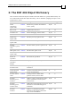
CANopen DSP 402 Implementation Guide 4 MAN-CAN402IG (Ver. 1.2) 2: The DSP 402 Object Dictionary This section describes the objects related to the DSP 402 device specific functionality. For more information about the object dictionary, refer to the Elmo SimplIQ CANopen DS 301 Implementation Guide. Name Index Description Access Mappable? Abort connection option code 0x6007 Function to perform on heartbeat event.
CANopen DSP 402 Implementation Guide 5 MAN-CAN402IG (Ver. 1.2) Name Index Description Access Position window time 0x6068 Defines the time in which the position R/W within the position window indicates target reached. N Velocity sensor actual value 0x6069 Actual velocity as calculated from the R main velocity sensor, in increments. Y Velocity sensor selection code 0x606A Selects the velocity sensor reading from either the position or the velocity sensor.
CANopen DSP 402 Implementation Guide 6 MAN-CAN402IG (Ver. 1.2) Name Index Description Access Mappable? Homing offset 0x607C Defines offset from homing zero position to application zero position. R/W N Software position limit 0x607D Defines limits for demand position value and actual position value. R/W N Polarity 0x607E Sets polarity for position or speed command and actual value. R/W Y Max profile velocity 0x607F Defines limit to which a profile velocity speed is saturated.
CANopen DSP 402 Implementation Guide 7 MAN-CAN402IG (Ver. 1.2) Name Index Description Access Mappable? Position encoder resolution 0x608F Defines relation between motor revolution and position increments. R/W N Velocity encoder resolution 0x6090 Defines ratio of encoder increments/ sec per motor revolutions/sec.
CANopen DSP 402 Implementation Guide 8 MAN-CAN402IG (Ver. 1.2) Name Index Motor type 0x6402 Motor catalog number 0x6403 Motor manufacturer 0x6404 http motor catalog address Description Access Mappable? R/W N 32 characters. R/W N 32 characters.
CANopen DSP 402 Implementation Guide 9 MAN-CAN402IG (Ver. 1.2) 3: Emergencies Emergency messages are detailed in the SimplIQ CANopen Implementation Guide. 4: Predefinition Object 0x1000: Device type The object at index 1000h describes the device type and functionality. The SimplIQ returns 0x20192 for servo drive supporting DSP 402. Object 0x1001: Error register All bits are defined as in the SimplIQ CANopen Implementation Manual and CiA DS-301.
CANopen DSP 402 Implementation Guide 10 MAN-CAN402IG (Ver. 1.
CANopen DSP 402 Implementation Guide 11 MAN-CAN402IG (Ver. 1.2) Transmit PDO 2 is mapped to the binary interpreter result object, transmitted each time the binary interpreter completes its processing. The event behavior is set by object 0x2F20, defined in the SimplIQ CANopen Implementation Manual.
CANopen DSP 402 Implementation Guide 12 MAN-CAN402IG (Ver. 1.2) 5: Common Entries 5.1 Drive Error The drive functionality in case of an error is determined using the following objects: 6007h: defined according to the SimplIQ CANopen Implementation Manual. 603Fh: reflects the 16 lower bits of object 0x1003, which, together with this object, get the emergency value regardless of the emergency message mask in object 2F21h.
CANopen DSP 402 Implementation Guide MAN-CAN402IG (Ver. 1.2) Object 0x603F: Error code This object captures the code of the last error that occurred in the drive. It corresponds to the value of the lower 16 bits of object 1003h, pre-defined error field. Object description: Index 603Fh Name Error code Object code VAR Data type UNSIGNED16 Category Optional Entry description: Access Read only PDO mapping No Value range UNSIGNED16 Default value 0 5.
CANopen DSP 402 Implementation Guide MAN-CAN402IG (Ver. 1.2) This object contains information for the user only and does not convey the value of the CA[28] command at the calibration procedure of a drive.
CANopen DSP 402 Implementation Guide MAN-CAN402IG (Ver. 1.2) Object 0x6404: Motor manufacturer This object gives the motor manufacturer’s name. The maximum length of this object is 32 characters. Object description: Index 6404h Name Motor manufacturer Object code VAR Data type VISIBLE_STRING Category Optional Entry description: Access Read/Write PDO mapping No Value range Default value Objects of data type VISIBLE_STRING have 32 characters.
CANopen DSP 402 Implementation Guide MAN-CAN402IG (Ver. 1.2) Object 0x6407: Motor service periods Value, in hours, of the nominal motor lifetime. The motor needs servicing after this time. Object description: Index 6407h Name Motor service period Object code VAR Data type UNSIGNED32 Category Optional Entry description: 5.3 Access Read/Write PDO mapping No Value range Unsigned32 Default value No Drive Data Objects 6500h to 65FFh serve as a database for drive parameters.
CANopen DSP 402 Implementation Guide 17 MAN-CAN402IG (Ver. 1.
CANopen DSP 402 Implementation Guide MAN-CAN402IG (Ver. 1.2) Object 0x6505: http drive catalog address This object gives the Internet address of the drive manufacturer. Object description: Index 6505h Name http drive catalog address Object code VAR Data type VISIBLE_STRING Category Optional Entry description: Access Read only PDO mapping No Value range Default value http:\\www.elmomc.
CANopen DSP 402 Implementation Guide 19 MAN-CAN402IG (Ver. 1.2) Data description: 31 22 Manufactu rer specific 21 16 Digital input 1…10 logic state 15 4 Reserved 3 Interlock 2 Home switch 1 Positive limit switch 0 Negative limit switch MSB The switch must be “active high.” Notes: The interlock is always 0. “Active high” means that the bit is set to high when the switch is logically active. Bits 16 – 25 reflect the logic active state of the digital inputs, starting from 1.
CANopen DSP 402 Implementation Guide 20 MAN-CAN402IG (Ver. 1.2) 6: Device Control 6.1 Objects 6040h: controlword 6041h: statusword The Device Control function block controls all functions of the device, categorized as: Device control of the state machine Operation mode functions The state of the device is controlled by the controlword, while the status of the device is indicated by the statusword. The state machine is controlled externally by the controlword and external signals.
CANopen DSP 402 Implementation Guide 21 MAN-CAN402IG (Ver. 1.2) States may be changed using the controlword and/or according to internal events. The current state can be read using the statusword.
CANopen DSP 402 Implementation Guide MAN-CAN402IG (Ver. 1.2) Drive States The following states of the device are possible: * NOT READY TO SWITCH ON: Low-level power (24V) has been applied to the drive. The drive is being initialized and is running the self test. A brake output, if present, is applied in this state. The drive function is disabled. This state is an internal state in which communication is enabled only at the end. The user can neither retrieve nor monitor this state.
CANopen DSP 402 Implementation Guide MAN-CAN402IG (Ver. 1.2) * QUICK STOP ACTIVE: The drive parameters may be changed. The quick stop function is being executed. The drive function is enabled and power is applied to the motor. According to the quick stop option code, the drive stops the motion and either stays in quick stop or disables the motor. The term “drive stops” means that the rfg completed the deceleration trajectory and not that the motor is stationary.
CANopen DSP 402 Implementation Guide MAN-CAN402IG (Ver. 1.2) State Transition 4: SWITCHED ON => OPERATION ENABLE Event: Enable Operation command received from host. Action: The drive function is enabled. State Transition 5: OPERATION ENABLE => SWITCHED ON Event: Disable Operation command received from host. Action: The drive operation is disabled. State Transition 6: SWITCHED ON => READY TO SWITCH ON Event: Shutdown command received from host. Action: The power section is switched off.
CANopen DSP 402 Implementation Guide MAN-CAN402IG (Ver. 1.2) After leaving FAULT state, the Fault Reset bit of the controlword must be cleared by the host. The drive does not monitor this bit in other states. If this bit is not cleared from a previous fault state, when the next fault occurs, the drive automatically enters SWITCH ON DISABLED state with no indications or warning. State Transition 16: QUICK STOP ACTIVE=>OPERATION ENABLE Event: Enable Operation command received from host.
CANopen DSP 402 Implementation Guide MAN-CAN402IG (Ver. 1.2) Illegal Transition After initiation of a drive by either power on or NMT node reset, the drive automatically performs transitions 0 and 1 to the SWITCH ON DISABLED state. The controlword can then be used to cause any of the transitions defined previously. If a transition is illegal (such as requesting a QUICK STOP in a FAULT state), the controlword is rejected with abort code 0609 0030, “Value range of parameter exceeded.
CANopen DSP 402 Implementation Guide 27 MAN-CAN402IG (Ver. 1.
CANopen DSP 402 Implementation Guide 28 MAN-CAN402IG (Ver. 1.2) Bits 4, 5, 6 and 8: These bits are operation-mode specific. Their description is found in the chapter about the special mode.
CANopen DSP 402 Implementation Guide MAN-CAN402IG (Ver. 1.
CANopen DSP 402 Implementation Guide 30 MAN-CAN402IG (Ver. 1.2) Bit 4: Voltage Enabled: High voltage is applied to the drive when this bit is set to 1. Bit 5: Quick Stop: When reset, this bit indicates that the drive is reacting to a Quick Stop request. Bits 0, 1 and 2 of the statusword must be set to 1 to indicate that the drive is capable of regenerating. The setting of the other bits indicates the status of the drive (for example, the drive is performing a quick stop in reaction to a non-fatal fault.
CANopen DSP 402 Implementation Guide MAN-CAN402IG (Ver. 1.2) Not all modes mentioned in the table are implemented in Elmo servo drives. Bits 14 and 15: These bits are reserved. They are not used and are set to 0. 6.
CANopen DSP 402 Implementation Guide MAN-CAN402IG (Ver. 1.
CANopen DSP 402 Implementation Guide MAN-CAN402IG (Ver. 1.2) Data description: Value Description -32,768…-1 Manufacturer specific 0 Disable drive function 1 Slow down on slow-down ramp; disable drive function 2…32,767 Reserved An attempt to set an unsupported value causes the transmission of abort code 0609 0030, value exceeded. Object 0x605C: Disable operation option code This parameter determines which action should be taken in case of the transition: OPERATION ENABLE => SWITCHED ON.
CANopen DSP 402 Implementation Guide MAN-CAN402IG (Ver. 1.2) Object 0x605D: Halt option code This parameter determines which action should be taken if bit 8 (halt) in the controlword is active.
CANopen DSP 402 Implementation Guide MAN-CAN402IG (Ver. 1.
CANopen DSP 402 Implementation Guide MAN-CAN402IG (Ver. 1.2) 7: Modes of Operation 6060h: Modes of operation 6061h: Modes of operation display 7.1 Functional Description The drive behavior depends on the activated modes of operation. Different modes can be implemented, although not in parallel. Therefore, the user must activate the required function by selecting a mode of operation. The modes-of-operation variables are initialized at reset to “no mode” (value -1).
CANopen DSP 402 Implementation Guide MAN-CAN402IG (Ver. 1.2) Data description: Value Description -128…-2 Reserved -1 No mode 0 Reserved 1 Profile position mode 2 Velocity (not supported) 3 Profiled velocity mode 4 Torque profiled mode 5 Reserved 6 Homing mode 7 Interpolated position mode 8…127 Reserved Notes: A read of this object shows only the value of modes of operation. The actual mode of the drive is reflected in the modes of operation display object.
CANopen DSP 402 Implementation Guide MAN-CAN402IG (Ver. 1.
CANopen DSP 402 Implementation Guide 39 MAN-CAN402IG (Ver. 1.2) 8.3 Objects Object 0x607E: Polarity Position demand value and position actual value are multiplied by 1 or -1, depending on the value of the polarity flag. Object description: Index 607Eh Name Polarity Object code VAR Data type UNSIGNED8 Category Optional Entry description: Access Read/write PDO mapping Yes Value range UNSIGNED8 Default value 0 Data Description 7 Position polarity 6 Velocity polarity 5 ...
CANopen DSP 402 Implementation Guide MAN-CAN402IG (Ver. 1.2) Object 0x6089: Position notation index This index is used to scale position objects. The unit is defined by the physical dimensions and calculated by unit type and exponent, declared in the dimension/ notation index tables (refer to Appendix A and Appendix B). Notes: The Elmo drive does not use this object; it is available for user convenience. The object is not checked for value and consistency.
CANopen DSP 402 Implementation Guide MAN-CAN402IG (Ver. 1.2) Entry description: Access Read/write PDO mapping No Value range UNSIGNED8 Default value — Object 0x608B: Velocity notation index This object defines the velocity notation index. The unit is defined by the physical dimensions and calculated by unit type and exponent, declared in the dimension/ notation index tables (refer to Appendix A and Appendix B). Notes: The Elmo drive does not use this object; it is available for user convenience.
CANopen DSP 402 Implementation Guide MAN-CAN402IG (Ver. 1.2) Object 0x608C: Velocity dimension index This object defines the velocity dimension index, which is used together with the velocity notation index (object 0x608B) to define a unit (refer to Appendix A and Appendix B). Notes: The Elmo drive does not use this object; it is available for user convenience. The object is not checked for value and consistency. This object is non-volatile.
CANopen DSP 402 Implementation Guide MAN-CAN402IG (Ver. 1.2) Entry description: Access Read/write PDO mapping No Value range INTEGER8 Default value — Object 0x608E: Acceleration dimension index This object defines the acceleration dimension index, which is used together with the acceleration notation index (object 0x608D) to define a unit (refer to Appendix A). Notes: The Elmo drive does not use this object; it is available for user convenience. The object is not checked for value and consistency.
CANopen DSP 402 Implementation Guide MAN-CAN402IG (Ver. 1.
CANopen DSP 402 Implementation Guide MAN-CAN402IG (Ver. 1.2) Object 0x6090: Velocity encoder resolution This object defines the ratio of encoder increments/second per motor revolutions/ second.
CANopen DSP 402 Implementation Guide MAN-CAN402IG (Ver. 1.2) Object 0x6093: Position factor This object converts the desired position (in position units) into the internal format (in increments). The object entries are the numerator and the divisor.
CANopen DSP 402 Implementation Guide MAN-CAN402IG (Ver. 1.2) Notes: The position factor is calculated according to this object regardless of the setting of any other objects, such as 0x608F (position encoder resolution). The actual value range of the divisor may not exceed 16,383 due to numeric overflow. Object 0x6094: Velocity encoder factor This object converts the desired velocity (in velocity units) into the internal format (in increments/second).
CANopen DSP 402 Implementation Guide MAN-CAN402IG (Ver. 1.2) Sub-index 2 Description Divisor Entry category Optional Access Read/write PDO mapping No Value range UNSIGNED32 Default value 1 Notes: The position factor is calculated according to this object regardless of the setting of any other objects, such as 0x6090 (velocity encoder resolution). The actual value range of the divisor may not exceed 16,383 due to numeric overflow.
CANopen DSP 402 Implementation Guide MAN-CAN402IG (Ver. 1.2) Sub-index 1 Description Numerator Entry category Optional Access Read/write PDO mapping No Value range UNSIGNED32 Default value 1 Sub-index 2 Description Divisor Entry category Optional Access Read/write PDO mapping No Value range UNSIGNED32 Default value 1 Notes: The velocity factor 1 is calculated according to this object regardless of the setting of any other objects, such as 0x6092 (feed constant).
CANopen DSP 402 Implementation Guide MAN-CAN402IG (Ver. 1.
CANopen DSP 402 Implementation Guide MAN-CAN402IG (Ver. 1.2) Object 0x6097: Acceleration factor This object converts the acceleration (in acceleration units/second2) into the internal format (in increments/second2).
CANopen DSP 402 Implementation Guide MAN-CAN402IG (Ver. 1.2) Notes: The acceleration factor is calculated according to this object regardless of the setting of any other objects, such as 0x6094 (velocity encoder factor). The actual value range of the divisor may not exceed 16,383 due to numeric overflow.
CANopen DSP 402 Implementation Guide MAN-CAN402IG (Ver. 1.2) 9: Homing 607Ch: Home offset 6098h: Homing method 6099h: Homing speeds 609Ah: Homing acceleration 9.1 General Information This chapter describes the method by which a drive seeks the home position (also called the datum, reference point or zero point).
CANopen DSP 402 Implementation Guide MAN-CAN402IG (Ver. 1.2) Name Value Description Homing operation start 0 Homing mode inactive. 0→1 Start homing mode. 1 Homing mode active. 1→0 Interrupt homing mode. 0 Execute the instruction of bit 4. 1 Stop axle with homing deceleration. Halt Notes: If homing is interrupted by setting bit 4 from “1” to “0”, the movement of the motor is not interrupted; that is, the motor remains in its present state, either moving or not.
CANopen DSP 402 Implementation Guide 55 MAN-CAN402IG (Ver. 1.2) 9.2 Objects Object 0x607C: Home offset This object is the difference between the zero position for the application and the machine home position (found during homing), measured in position units. During homing, the machine home position is found. Once homing is completed, the zero position is offset from the home position by adding the home offset to the home position.
CANopen DSP 402 Implementation Guide MAN-CAN402IG (Ver. 1.2) Object 0x6098: Homing method This object determines the method used during homing.
CANopen DSP 402 Implementation Guide MAN-CAN402IG (Ver. 1.2) Object 0x6099: Homing speeds This entry in the object dictionary defines the speeds used during homing, in velocity units. The value is normalized to increments by velocity code factor. Typically, a high speed is used when searching for a home switch and the slow speed is used when searching for the index.
CANopen DSP 402 Implementation Guide MAN-CAN402IG (Ver. 1.2) The speed is submitted to the maximum speed limit given by the user during setup. Otherwise, an abort message with abort code 0609 0030, “Value range of parameter exceeded” is activated. If the limits have been changed during the process, the drive enters a fault state.
CANopen DSP 402 Implementation Guide MAN-CAN402IG (Ver. 1.2) Various homing positions are illustrated in the diagrams that follow (section 9.4). A circled number indicates the code for selecting the homing position. The direction of movement is also indicated. Additional homing methods are available with other modes of the Elmo drives, such as the binary interpreter or the user program.
CANopen DSP 402 Implementation Guide MAN-CAN402IG (Ver. 1.2) 9.4 DSP 402 Homing Methods The following sub-sections describe the details of how each homing mode functions. The Elmo drives support each of these methods. 9.4.1 Method 1: Homing on the negative limit switch and index pulse Using this method, the initial direction of movement is leftward if the negative limit switch is inactive (here shown as low).
CANopen DSP 402 Implementation Guide MAN-CAN402IG (Ver. 1.2) 9.4.3 Methods 3 and 4: Homing on the positive home switch and index pulse Using methods 3 or 4, the initial direction of movement is dependent on the state of the home switch. The home position is at the index pulse to either the left or right of the pint where the home switch changes state.
CANopen DSP 402 Implementation Guide MAN-CAN402IG (Ver. 1.2) 9.4.5 Methods 7 to 14: Homing on the home switch and index pulse These methods use a home switch that is active over only a portion of the travel; in effect, the switch has a “momentary” action as the axle position sweeps past the switch.
CANopen DSP 402 Implementation Guide MAN-CAN402IG (Ver. 1.2) 9.4.6 Methods 15 and 16: Reserved These methods are reserved for future expansion of the homing mode. 9.4.7 Methods 17 to 30: Homing without an index pulse These methods are similar to methods 1 to 14, except that the home position is not dependent on the index pulse; it is dependent only on the relevant home or limit switch transitions.
CANopen DSP 402 Implementation Guide MAN-CAN402IG (Ver. 1.2) 10: Position Control Function 6062h: Position demand value in position units 6063h: Position actual value in increments 6064h: Position actual value 6065h: Following error window 6067h: Position window 6068h: Position window time out 60F4h: Following error actual value 60FAh: Position control effort 60FCh: Position demand value in increments 10.
CANopen DSP 402 Implementation Guide MAN-CAN402IG (Ver. 1.2) 10.2 Objects Object 0x6062: Position demand value The value of this object is taken from the internal position command and is given in position units after being converted by position factor.
CANopen DSP 402 Implementation Guide MAN-CAN402IG (Ver. 1.2) Object 0x6064: Position actual value This object represents the actual value of the position measurement device, in userdefined units. When dual loop mode is active (UM=4), this object returns the value of the position sensor as derived from the load feedback (PY command); in all single loop modes (UM = 1,2,3,5), it returns the motor position feedback (PX command) value.
CANopen DSP 402 Implementation Guide MAN-CAN402IG (Ver. 1.2) Entry description: Access Read/write PDO mapping No Value range UNSIGNED32 Default value 0 Object 0x6066: Following error time out When a following error occurs longer than the defined value of the timeout, given in multiples of milliseconds, the corresponding bit 13 following error in the statusword is set to 1. No further reaction is taken. The Elmo drive setup parameter for position following error is ER[3].
CANopen DSP 402 Implementation Guide MAN-CAN402IG (Ver. 1.2) Object 0x6067: Position window This object defines a symmetrical range of accepted positions relative to the target position. If the actual value of the position encoder is within the position window, this target position is regarded as reached. Because the position window is usually specified in userdefined units, the position factor must be used to transform this value into increments.
CANopen DSP 402 Implementation Guide MAN-CAN402IG (Ver. 1.2) Entry description: Access Read/write PDO mapping No Value range UNSIGNED16 (note in object 6067h) Default value 20 Object 0x60FC: Position demand value - increments This output of the trajectory generator in profile position mode is an internal value using increments.
CANopen DSP 402 Implementation Guide MAN-CAN402IG (Ver. 1.2) 11: Profiled Position 607Ah: Target position 607Bh: Position range limit 607Dh: Software position limit 607Fh: Maximum profile velocity 6081h: Profiled velocity 6082h: End velocity 6083h: Profiled acceleration 6084h: Profiled deceleration 6086h: Motion profile type 60C5h: Maximum acceleration 60C6h: Maximum deceleration 11.
CANopen DSP 402 Implementation Guide MAN-CAN402IG (Ver. 1.2) Name Value Description New set-point 0 Does not assume target position. 1 Assumes target position. 0 Finish actual positioning and then start next positioning. 1 Interrupt actual positioning and start next positioning. 0 Target position is an absolute value. 1 Target position is a relative value. 0 Execute positioning. 1 Stop axle with profile acceleration. 0 New set point is not buffered. 1 New set point is buffered.
CANopen DSP 402 Implementation Guide MAN-CAN402IG (Ver. 1.2) 11.2 Objects Object 0x607A: Target position The target position is the position to which the drive should move in position profile mode, using the current settings of motion control parameters such as velocity, acceleration, deceleration and motion profile type. The target position is given in userdefined position units. It is converted to position increments using the position factor.
CANopen DSP 402 Implementation Guide MAN-CAN402IG (Ver. 1.
CANopen DSP 402 Implementation Guide MAN-CAN402IG (Ver. 1.2) Object 0x607D: Software position limit This object contains the sub-parameters min position limit and max position limit, which define the absolute position limits for the position demand value and the position actual value. Every new target position must be checked against these limits. The position limits are specified in position units (same as target position) and are always relative to the machine home position.
CANopen DSP 402 Implementation Guide MAN-CAN402IG (Ver. 1.2) Sub-index 2 Description Max position limit Entry category Mandatory Access Read/write PDO mapping No Value range INTEGER32 Default value No The value of the software position limit is reflected in the VH[3] and VL[3] commands, to which the range and restrictions are ultimately submitted (refer to the SimplIQ Command Reference Manual).
CANopen DSP 402 Implementation Guide MAN-CAN402IG (Ver. 1.2) Object 0x6081: Profile velocity This object is the velocity normally attained at the end of the acceleration ramp during a profiled move and is valid for both directions of motion. The profile velocity is given in user-defined speed units. It is converted to position increments per second using the velocity encoder factor.
CANopen DSP 402 Implementation Guide MAN-CAN402IG (Ver. 1.2) Object 0x6083: Profile acceleration The profile acceleration is given in user-defined acceleration units. It is converted to position increments per second2 using the normalizing factors.
CANopen DSP 402 Implementation Guide MAN-CAN402IG (Ver. 1.2) The value of the profile deceleration is reflected in the DC command, to which the range and restrictions are ultimately submitted (refer to the SimplIQ Command Reference Manual). Object 0x6085: Quick stop deceleration The quick stop deceleration is the deceleration used to stop the motor if the Quick Stop command is given and the quick stop option code (see 605Ah) is set to 2.
CANopen DSP 402 Implementation Guide MAN-CAN402IG (Ver. 1.2) Data description: Value Description -32,768…-1 Manufacturer specific 0 Linear ramp (trapezoidal profile) 1 Not supported 2 Not supported 3 Not supported 4…32,767 Reserved 11.
CANopen DSP 402 Implementation Guide MAN-CAN402IG (Ver. 1.2) 5. Unless it was interrupted by a change set immediately, the next trajectory is executed as soon as a target reached is set. Notes: A target position can be programmed at any status but can be executed only in ENABLE OPERATION state. Otherwise, an emergency message is transmitted. The amount of buffered data can be received by object 0x2F15.
CANopen DSP 402 Implementation Guide MAN-CAN402IG (Ver. 1.2) 12: Interpolated Position 60C0h: Interpolation sub mode select 60C1h: Interpolation data record 60C2h: Interpolation time period 60C3h: Interpolation sync definition 60C4h: Interpolation data configuration 12.1 General Information Interpolated Position mode is used to control multiple coordinated axles or a single axle with the need for time-interpolation of set-point data.
CANopen DSP 402 Implementation Guide MAN-CAN402IG (Ver. 1.2) Interpolation inactive The state entered when the device is in OPERATION ENABLED state and Interpolated Position mode is selected and displayed (object 0x6061). The drive unit accepts input data and buffers it for interpolation calculations, but does not move the axles. Interpolation active The state entered when the device is in OPERATION ENABLED state, the interpolated position mode is selected and it is enabled.
CANopen DSP 402 Implementation Guide MAN-CAN402IG (Ver. 1.2) Controlword of Interpolated Position mode: Name Value Description Enable ip mode 0 Interpolated position mode is inactive. 1 Interpolated position mode is active. 0 Execute the instruction of bit 4. 1 Stop axle according to halt option code. Halt Notes: If the interpolation is interrupted by setting bit 4 from 1 to 0, the drive stops at quick stop deceleration (object 0x6085) and is treated similarly to axis halted.
CANopen DSP 402 Implementation Guide MAN-CAN402IG (Ver. 1.2) 12.2 Objects Object 0x60C0: Interpolation sub mode select This object reflects or changes the actual chosen interpolation mode, selected by the user. The interpolation sub-modes can be changed only when the interpolated mode is inactive. When modifying the interpolation mode, a new mapping (if needed) of object 0x60C1 must be made after the sub mode is modified. Failing to do so may cause unpredictable results.
CANopen DSP 402 Implementation Guide MAN-CAN402IG (Ver. 1.2) Object 0x60C1: Interpolation data record This object is the data words, which are necessary for performing the interpolation algorithm. The interpretation of the data words may vary with the different possible interpolation modes as set by 60C0h.
CANopen DSP 402 Implementation Guide MAN-CAN402IG (Ver. 1.2) Object 0x60C2: Interpolation time period This object is used to define the relative time taken between two set points for the interpolation position modes. The interpolation time unit is given in 10interpolation time index seconds. The interpolation time period can be changed only when the interpolated mode is inactive.
CANopen DSP 402 Implementation Guide MAN-CAN402IG (Ver. 1.2) Object 0x60C3: Interpolation sync definition Devices in the interpolation position mode often interact with other devices. Therefore it is necessary to define a communication object, which is used to synchronize these interactions. This can be done by the general Sync as described in /3/, or a specific group-sync-signal. Each reception of this trigger-signal or a specified number of occurrences of the trigger-signal can synchronize the devices.
CANopen DSP 402 Implementation Guide MAN-CAN402IG (Ver. 1.2) Object 0x60C4: Interpolation data configuration The interpolation data configuration enables the user to get information about the buffer size and set the buffer configuration and strategy.
CANopen DSP 402 Implementation Guide MAN-CAN402IG (Ver. 1.
CANopen DSP 402 Implementation Guide MAN-CAN402IG (Ver. 1.2) Sub-index 6 Description Buffer clear Entry category Mandatory Access Write only PDO mapping No Value range UNSIGNED8 (described below) Default value 0 Notes: The maximum and actual buffer size are the number of interpolated data records that may be sent to the drive to fill the input buffer. They are not the size in bytes. The actual buffer size may be between max buffer size to.
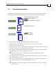
CANopen DSP 402 Implementation Guide 91 MAN-CAN402IG (Ver. 1.2) 12.3 Functional Description In Interpolated Position mode, the drive executes a time-synchronized motion path. The user specifies the value of the reference signal at an initial time, and at fixed-time intervals from then on (as in the following figure). P4 P3 P1 P0 P2 ∆T T start ∆T ∆T ∆T Time Figure 9: Interpolated Motion In the figure, the time interval ∆T is set by the object 0x60c2, in milliseconds.
CANopen DSP 402 Implementation Guide 92 MAN-CAN402IG (Ver. 1.2) 12.3.1 Linear Interpolation Linear interpolation requires only the position specified in data record object 0x60C1. The structure of the position data is according to data type 0x41 (refer to the Elmo CANopen Implementation Guide). The velocity at each time point is calculated by finding the difference between the corresponding position and the position of the previous point, as in the following figure.
CANopen DSP 402 Implementation Guide MAN-CAN402IG (Ver. 1.2) 12.3.3 Motion Synchronization The IP mode enables the synchronized motion of multiple axes. The motions of several slave axes are synchronized if they all run IP, and they all being the IP at the same time. Synchronization can proceed continuously using the SYNC-Time stamp mechanism. In order to start several axes synchronously, map the controlword to a synchronous RPDO, and then use the mapped controlword to enable interpolation for all axes.
CANopen DSP 402 Implementation Guide MAN-CAN402IG (Ver. 1.2) 13: Profiled Velocity 6069h: Velocity sensor actual value 6060h: Velocity window 606Ah: Sensor selection code 606Bh: Velocity demand value 606Ch: Velocity actual value 606Dh: Velocity window 606Eh: Velocity window time 606Fh: Velocity threshold 6070h: Velocity threshold time 60FFh: Target velocity 13.
CANopen DSP 402 Implementation Guide MAN-CAN402IG (Ver. 1.2) Controlword of the profiled velocity mode: Bit Function 0…3 Described in Device Control 4… Reserved 7 Described in Device Control 8 Halt 9…15 Described in Device Control 14..15 Described in Device Control Name Value Description Halt 0 Execute the motion. 1 Stop axle.
CANopen DSP 402 Implementation Guide MAN-CAN402IG (Ver. 1.2) 13.2 Objects Object 0x6069: Velocity sensor actual value This object describes the value read from a velocity encoder, in increments/second. If the velocity sensor actual value is reflected by object 0x606C, it is scaled by position_factor_2 and by position_factor_1.
CANopen DSP 402 Implementation Guide MAN-CAN402IG (Ver. 1.2) Data description: Value Description 0000h Actual velocity value from position encoder 0001h Actual velocity value from velocity encoder 0002h…7FFFh Reserved 8000h…FFFFh Manufacturer specific Object 0x606B: Velocity demand value The value of the velocity command as reflected by the trajectory generator. This value is scaled by velocity_factor_1.
CANopen DSP 402 Implementation Guide MAN-CAN402IG (Ver. 1.2) Object 0x606C: Velocity actual value This object is represented in velocity units and is coupled with the velocity used as input to the velocity controller. The object is taken from either the position sensor or the velocity sensor. In UM=5 (single position loop), this object reflects the load and the motor value; in UM=4 (dual loop), object 0x606A determines which sensor is reflected.
CANopen DSP 402 Implementation Guide MAN-CAN402IG (Ver. 1.2) Object 0x606E: Velocity window time The corresponding bit 10 target reached is set in the statusword when the difference between the target velocity and the velocity actual value is within the velocity window longer than the velocity window time. The value of the velocity window time is given in multiples of milliseconds.
CANopen DSP 402 Implementation Guide MAN-CAN402IG (Ver. 1.2) Object 0x6070: Velocity threshold time The velocity threshold time is given in multiples of milliseconds. See the description in object 0x606F.
CANopen DSP 402 Implementation Guide MAN-CAN402IG (Ver. 1.2) 14: Profiled Torque Mode 6071h: Target torque 6072h: Max torque 6073h: Max current 6074h: Torque demand value 6075h: Motor rated current 6076h: Motor rated torque 6077h: Torque actual value 6078h: Current actual value 6087h: Torque slope 6088h: Torque profile type 14.1 General Information This chapter describes the profile torque mode. The profile torque mode allows a host (external) control system (i.e.
CANopen DSP 402 Implementation Guide MAN-CAN402IG (Ver. 1.2) The torque demand, torque actual value, current actual value may be available to the user as parameters, if they are monitored. Elmo’s SimplIQ drives support Profile Torque mode when selected. When Profile Torque objects are set, some internal commands are affected. These internal commands remain even after another operating mode is chosen.
CANopen DSP 402 Implementation Guide MAN-CAN402IG (Ver. 1.2) Statusword of the profiled velocity mode: Bit Function 0…9 Described in Device Control 10 Target reached 11…13 Reserve 14…15 Described in Device Control Name Value Description Target reached 0 Target torque not (yet) reached. 1 Target torque reached. 14.2 14.2.1 Objects dictionary entries Objects defined in other chapters 6040h Controlword 6041h Statusword 14.2.
CANopen DSP 402 Implementation Guide MAN-CAN402IG (Ver. 1.2) Example: If a torque that is relative to current of 2 amps is needed, and object 0x6075 (Motor Rate Current) is 3200 mA, then [0x6071] = 2000 mA x 1000 / 3200 mA = 625 This number means 62.5 % of Motor Rate Current. Object 0x6072: Max torque This value represents the maximum permissible torque in the motor and is given per thousand of rated torque.
CANopen DSP 402 Implementation Guide MAN-CAN402IG (Ver. 1.2) Entry description: Access Read/write PDO mapping No Value range INTEGER16 Default value 0 Note: The value in 6073h (which is in mA) is entered in PL[1] after it is converted to Amperes.
CANopen DSP 402 Implementation Guide MAN-CAN402IG (Ver. 1.2) Object 0x6075: Motor Rate Current This value is taken from the motor nameplate and is entered in multiples of milliamp. Depending on the motor and drive technology this current may be either DC, peak or rms (root-mean-square) current. All relative current data refers to this value.
CANopen DSP 402 Implementation Guide MAN-CAN402IG (Ver. 1.2) Object 0x6077: Torque Actual value The torque actual value corresponds to the instantaneous torque in the drive motor. The value is given in units of per thousand of rated torque.
CANopen DSP 402 Implementation Guide MAN-CAN402IG (Ver. 1.2) Object 0x6087: Torque slope This parameter describes the rate of change of torque in units of per thousand of rated torque per second.
CANopen DSP 402 Implementation Guide 109 MAN-CAN402IG (Ver. 1.
CANopen DSP 402 Implementation Guide 110 MAN-CAN402IG (Ver. 1.