Elmo Motion Control CANopen DSP 305 Implementation Guide Version 1.
Important Notice This guide is delivered subject to the following conditions and restrictions: This guide contains proprietary information belonging to Elmo Motion Control Ltd. Such information is supplied solely for the purpose of assisting users of SimplIQ servo drives in implementing CANopen networking. The text and graphics included in this manual are for the purpose of illustration and reference only. The specifications on which they are based are subject to change without notice.
CANopen DSP 305 Implementation Guide MAN-CAN305IG (Ver. 1.1) Contents 1 1.1 1.2 1.3 1.4 1.5 Introduction ................................................................................................................ 1-1 Objectives of LSS ......................................................................................................... 1-1 Abbreviations and Terms ...........................................................................................
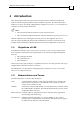
CANopen DSP 305 Implementation Guide MAN-CAN305IG (Ver. 1.1) 1 Introduction This document describes the objects and operational modes of the Elmo DSP-based motion controller implementation of the CiA DSP 305 protocol. The Elmo Harmonica digital servo drive (part of the SimplIQ family of digital servo drives ) is used whenever examples are shown in this document. Notes: The DSP in CiA DSP 305 stands for Draft Standard Proposal.
CANopen DSP 305 Implementation Guide 1-2 MAN-CAN305IG (Ver. 1.1) LMT (Layer Management): Functions to inquire and change the settings of certain parameters of the local layers on a CAL module. LSS (Layer Setting Services): Functions to inquire and change the settings of certain parameters of the local layers on a CANopen network.
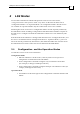
CANopen DSP 305 Implementation Guide MAN-CAN305IG (Ver. 1.1) 1.5 Elmo Documentation This manual – included in the Elmo CANopen Implementation Guide – is part of the Elmo SimplIQ digital servo drive documentation set, as outlined in the following diagram: In addition to this document, the SimplIQ documentation set includes: The Harmonica, Bassoon, Cello and Cornet Installation Guides, which provides full instructions for installing SimplIQ digital servo drives.
CANopen DSP 305 Implementation Guide MAN-CAN305IG (Ver. 1.1) 2 LSS Modes Devices that communicate with the LSS protocol can be in one of two modes, ‘Configuration Mode’ and ‘Operation Mode’. Any device on the network that is not in ‘Configuration Mode’ is in ‘Operation Mode’. In ‘Configuration Mode’ all LSS services are available. In ‘Operation Mode’ only the switch mode services are available. Switching the mode of a device to ‘Configuration Mode’ must be explicitly initiated by the LSS Master.
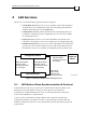
CANopen DSP 305 Implementation Guide 3-1 MAN-CAN305IG (Ver. 1.1) 3 LSS Services LSS services can be functionally grouped into four categories: Switch Mode Services provide a way to logically connect the LSS Master and LSS Slave(s) for configuration purposes. They change the LSS mode attribute of the LSS Slave (see the Figure 3-1). Configuration Services perform the actual task of configuring the layer parameters of LSS Slave(s). The configuration services are only available in configuration mode.
CANopen DSP 305 Implementation Guide 3-2 MAN-CAN305IG (Ver. 1.1) The protocols described below all have the same structure: a specific sequence of COBs are exchanged between the LSS Master and LSS Slave for a particular LSS service. Requesting Messages use COB-ID 7E5h while Response Messages use COB-ID 7E4h. LSS uses Command Specifiers (CS) to identify the commands. CSs from 00 - 03fh are reserved for use by the LMT. 040h - 07fh are reserved for use by standard LSS services.
CANopen DSP 305 Implementation Guide 3-3 MAN-CAN305IG (Ver. 1.1) 3.2.2 Switch Mode Selective This service is used to switch a specific LSS Slave device to configuration mode.
CANopen DSP 305 Implementation Guide 3-4 MAN-CAN305IG (Ver. 1.1) 3.3 Configuration Services Configuration services are available only in configuration mode. Some of the services are only available to one LSS Slave device. 3.3.1 Configuration Node-ID This service enables the LSS Master to configure the NMT-address of an LSS Slave. Only one LSS Slave at a time can be configured with this service. A remote result message confirms the success or failure of the service.
CANopen DSP 305 Implementation Guide 3-5 MAN-CAN305IG (Ver. 1.1) 3.3.2 Configuration Bit Timing Parameters The LSS Master’s Configure Bit Timing Parameters service sets new bit timing on an LSS Slave. The bit timing parameters for different baud rates are specified in the Bit Timing Parameter Table below. With table_selector value ´0´ the standard CiA bit timing parameter table is used. The table_index selects the entry (baud rate) in the selected table (value ‘0’ refers to the highest baud rate).
CANopen DSP 305 Implementation Guide 3-6 MAN-CAN305IG (Ver. 1.1) 3: out of range 3.3.3 Activate Bit Timing Parameters The LSS Master's Activate Bit Timing Parameters service activates the bit timing as defined by the Configure Bit Timing Parameters service. The switch_delay parameter specifies the length of two delay periods of equal length, which are necessary to avoid operating the bus with differing bit timing parameters.
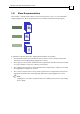
CANopen DSP 305 Implementation Guide 3-7 MAN-CAN305IG (Ver. 1.1) c ******** LMT Master d1 LMT Slave 1 t d2 t p2 d1 d2 ******** LMT Slave 2 p2 c: p1, p2: d1: d2: ********: d1 t d2 initiation of command individual processing delay duration of first switch_delay period duration of second switch_delay period node may be transmitting Figure 3-13 Switch_Delay Periods 3.3.
CANopen DSP 305 Implementation Guide 3-8 MAN-CAN305IG (Ver. 1.1) If error_code is 255, then a specific_error_code will be: 2: incorrect mode no other options at this time 3.4 Inquiry Services The inquiry services are available only in configuration mode. 3.4.1 Inquire LSS Address This service finds the LSS-address of a Slave in configuration mode. Since the LSS address has four parts (Vendor-ID, Product-Code, Revision-Number and SerialNumber), four inquiries are required.
CANopen DSP 305 Implementation Guide 3-9 MAN-CAN305IG (Ver. 1.
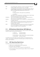
CANopen DSP 305 Implementation Guide 3-10 MAN-CAN305IG (Ver. 1.1) COB-ID = 7E4h 0 1 NID CS 94 2 3 ## 4 5 6 7 8 reserved for future use by CiA Figure 3-25 Confirm Node-ID If the Node-ID was recently changed with a Configure Node-ID command, the original Node-ID will continue to be returned until the next power on reset. A value of FFh is returned if the Node-ID is not configured … this is only possible if the slave is in ‘LSS Init State’. 3.
CANopen DSP 305 Implementation Guide 3-11 MAN-CAN305IG (Ver. 1.1) Revision-Number-Low: The lower boundary of the requested revision numbers range. The Minor range must be set to 0000h. COB-ID = 7E5h 0 1 CS 73 2 lsb 3 4 Revision-Number-High 5 msb 6 7 8 reserved for future use by CiA Figure 3-29 Slave Revision Number Inquiry Revision-Number-High: The higher boundary of the requested revision numbers range. The Minor range must be set to FFFFh.
CANopen DSP 305 Implementation Guide 3-12 MAN-CAN305IG (Ver. 1.1) COB-ID = 7E4h 1 0 CS 2 3 79 4 5 6 7 8 reserved for future use by CiA Figure 3-32 Slave Serial-Number Confirmation 3.5.
CANopen DSP 305 Implementation Guide MAN-CAN305IG (Ver. 1.1) 4 Implementation Rules When implementing the LSS protocols, the following rules must be followed to guarantee interoperability: CAL Layer Management (LMT) To distinguish between LMT and LSS, all LSS services must use command specifiers in the 040h – 07fh range. Invalid COB's A COB is invalid if it has a COB-ID that is used by the LSS Protocol, but contains invalid parameter values according to the LSS Protocol.