
User guide


1.2 Bassoon Connectors
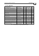
The table below presents the connector panel of the Bassoon and specifies the cable connectors.
Pins Type
Connector Manufacturer
and Part Number Port Connector Location
8 RJ-45
RJ-45 plug
J1, J8, J9
8 2 mm Pitch
Molex 35507-0800
J2, J5
12 2 mm Pitch
Molex 35507-1200
J3
2 2 mm Pitch
Molex 35507-0200
J4
4 2 mm Pitch
Molex 35507-0400
J6
3 2 mm Pitch
Molex 35507-0300
J7
7
5.08 mm Pitch
Terminal Block
Phoenix MSTB 2.5/7-ST-5.08
Main
power
Table 1-2: Connectors on the Bassoon Drive
1.3 Cable Cross Reference
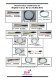
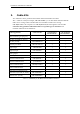
1.3.1 Harmonica
Cable Application Cable Part. No. Pins Pin Location Page
Main Feedback (general purpose) CBL-MLXFDBK-5 12 J3 3-1
Encoder (for SAR, SA, SB, SC) CBL-MTRENC1-5 12 J3 3-2
Encoder (for SE) CBL-MTRENC3-5 12 J3 3-3
Auxiliary Feedback CBL-MLXAUX-5 8 J2 4-1
Digital Input CBL-MLXDI-5 8 J5 5-1
Digital Output CBL-MLXDO-5 4 J6 6-1
Analog Input CBL-MLXAI-5 3 J7 7-1
Auxiliary Power CBL-MLX24-5 2 J4 8-1
RS-232 Communications (RJ-45) CBL-RJ452321-5 8 J1 9-1
RS-232 Communications (pitchfork) JCA-HAR11-5 3 of 8 See page 9.2 9-2
CAN Communications CBL-RJ45CAN1-5 8 J1 9-3
CAN Communications (daisy chain) CBL-RJ45CAN2 8 see page 9.4 9.4
Motor Power (general purpose) CBL-MTRPWR-5 4 PE/M1/M2/M3 10-1
Motor Power (for SAR, SA, SB, SC) CBL-MTRPWR1-5 4 PE/M1/M2/M3 10-2
Motor Power (for SE) CBL-MTRPWR2-5 4 PE/M1/M2/M3 10-3
Table 1-3: Cable and Pin Cross-Reference for the Harmonica Drive
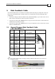
Auxiliary
Power
Supply
CANopen
Auxiliary
Feedback
Main
Feedback
Main
Power
CANopen
RS232
Digital
In
p
ut
Digital
Output
Analog
Input
Harmonica and Bassoon Cable Kits Introduction
MAN-CBLKIT- (Ver. 3.4)
1-2