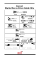
Cornet Digital Servo Drive Cable Kits COMM.1: (RS-232) CBL-RJ452321 CBL-RJ452321-5 COMM.2: (CAN) Analog Inputs: CBL-RJ45CAN1-5 CBL-RJ45CAN1-5 CBL-A001-5 CBL-A001-5 COMM.2: (CAN) COMMITED I/O: CBL-D002-5 (Digital Inputs) CBL-D002-5 Aux.
Important Notice This guide is delivered subject to the following conditions and restrictions: ! This guide contains proprietary information belonging to Elmo Motion Control Ltd. Such information is supplied solely for the purpose of assisting users of Elmo’s Cornet servo drives in assembling the required cables for their drive. ! The text and graphics included in this manual are for the purpose of illustration and reference only.
Cornet Cable Kits MAN-CBLKIT-COR (Ver. 1.0) Contents 1. Introduction ............................................................................................................................. 1 1.1 Cornet Connectors....................................................................................................................................... 1 1.2 Cable Cross-Reference................................................................................................................................
Cornet Cable Kits 1 MAN-CBLKIT-COR (Ver. 1.0) 1. Introduction This document provides the wiring details for the cables used to connect Cornet digital servo drives with the end-user application. The servo drive-side pinouts are provided in Chapter 3 of the drive’s installation guide. The cables come in two lengths: 2 meters (6 ½ feet) and 5 meters (16 ½ feet). The cable length is indicated in the cable part number by use of an extended suffix to indicate 5 meter length.
Cornet Cable Kits 2 MAN-CBLKIT-COR (Ver. 1.0) 1.2 Cable Cross-Reference No. of Pins Label on Cornet pg COM.1 4 Cable Application Cable Part. No. RS-232 Communications CBL-RJ452321-5 8 CAN Communications CBL-RJ45CAN1-5 8 CAN-CAN Daisy-Chain CBL-RJ45CAN2-5 8 Analog Inputs CBL-A001-5 ANALOG INPUTS 7 Digital Inputs CBL-D002-5 COMMITTED I/O 8 Digital Outputs CBL-D001-5 GENERAL I/O 9 Main Feedback (gnrl-purp.
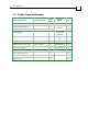
Cornet Cable Kits 3 MAN-CBLKIT-COR (Ver. 1.0) 2. Cable Kits Several Cable Kits can be purchased from Elmo. Each contain a set of 8 cables. The -5 suffix on the kits and on the cables (CBL-DFDBK-5 for example) indicate that the cables are 5m long. Cables and kits without that suffix are 2m long (except for CBL-RJ45CAN2 which is 20cm long). Customers may purchase cables in kits, or individually in multiples of 10 each. The contents of the kits are listed below: Cable Application Cable Part. No.
Cornet Cable Kits 4 MAN-CBLKIT-COR (Ver. 1.0) 3. Communication Cables The communication cables use 26-AWG twisted pair shielded cable. They are connected using an 8-pin RJ-45 plug. Elmo drives can communicate using the following options: ! RS-232, full duplex ! CANopen 3.1 RS-232 Serial Communications (CBL-RJ452321-5) RJ45 Pin No. Color D-type Female Pin No.
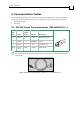
Cornet Cable Kits 5 MAN-CBLKIT-COR (Ver. 1.0) 3.2 CAN Communications (CBL-RJ45CAN1-5) RJ45 Pin No. Color D-type Female Pin No. Signal Description 1 Green 7 CAN-H CAN_H bus line 2 Yellow 2 CAN_L CAN_L bus line 3 White 3 CAN_GND CAN ground 4 — — — — 5 — — — — 7 — — — — 8 — — — — body Drain Wire body shield 1 cable shield The shields of the RJ-45 and D-type plugs are connected to each other through the cable braid. Figure 2: CAN Cable (Part No.
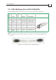
Cornet Cable Kits 6 MAN-CBLKIT-COR (Ver. 1.0) 3.3 CAN-CAN Daisy-Chain (CBL-RJ45CAN2) Cable CBL-RJ45CAN2 is 20 cm long, it is used for “daisy-chaining” CAN nodes. RJ45 Pin No. Color RJ45 Pin No.
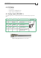
Cornet Cable Kits 7 MAN-CBLKIT-COR (Ver. 1.0) 4. I/O Cables • Analog Inputs • Digital Inputs ("COMMITTED I/O") • Digital Outputs ("GENERAL I/O") 4.1 Analog Inputs (CBL-A001-5) The digital input cable is a 24-AWG shielded cable. It is connected using an 9-pin D-sub plug.
Cornet Cable Kits 8 MAN-CBLKIT-COR (Ver. 1.0) 4.2 Digital Inputs (CBL-D002-5) The digital input cable is a 24-AWG shielded cable which attaches to the COMMITTED I/O port on the Cornet. It is connected using an 15-pin Hi-Density D-sub socket. Pin Color Signal Pair 1 Orange IN1 6 Cyan IN2 2 Grey IN3 7 Pink IN4 3 Brown IN5 8 White IN6 4 Red IN7 9 Blue IN8 5 Yellow IN9 10 Green IN10 11 Purple INRET1-2 Prog. Input return 1-2 12 Black INRET3-4 Prog.
Cornet Cable Kits 9 MAN-CBLKIT-COR (Ver. 1.0) 4.3 Digital Outputs (CBL-D001-5) The digital output cable is a 26-AWG shielded cable that is connected to the General I/O port on the Cornet. It is connected using a 15-pin Hi-Density D-sub plug.
Cornet Cable Kits 10 MAN-CBLKIT-COR (Ver. 1.0) 5. Feedback Cables The main feedback cables are made of 24-AWG shielded cable. The feedback cable has a 15pin D-sub plug which connects to the FEEDBACK A port on the Cornet. • The Main Feedback Cable (CBL-DFDBK) is open on the motor side so that it can be connected to customer-specific connectors. • Encoder Cable CBL-MTRENC2 has a 15-pole socket on the motor side for Metronix APM-SAR, SA, SB and SC motors.
Cornet Cable Kits 11 MAN-CBLKIT-COR (Ver. 1.0) 5.2 Auxiliary Feedback Cable (CBL-DAUX-5) The auxiliary feedback cable is a 24-AWG shielded cable. It is connected using an 15-pin Dsub plug which connects to the Cornet’s FEEDBACK B port.
Cornet Cable Kits 12 MAN-CBLKIT-COR (Ver. 1.0) 6. Power Cables 6.1 Auxiliary Power Cable (CBL-CEL24-5) The auxiliary power cable is a 24-AWG shielded cable terminated by pins on the SimplIQ side. The pins are screwed into the 2-pole Pheonix Terminal Block provided with the Cornet. Pin No. Color 1 Red 2 Black Twisted & Shielded Wire Signal Pair Description +24VDC +24 VDC auxiliary power supply RET24VDC Return (common) of 24 VDC auxiliary power supply Figure 9: Auxiliary Power Cable (Part No.
Cornet Cable Kits 13 MAN-CBLKIT-COR (Ver. 1.0) 6.3 Motor Cable (CBL-MTRPWR1-5) CBL-MTRPWR1-5 is a 24-AWG shielded cable in which each wire, on the SimplIQ drive side, is connected to a pin terminal and the wires on the motor side are connected to a 4pole socket. This cable is designed for connecting a Cornet to a Metronix APM-SAR, SA, SB or SC motor. Signal Drive Side Color Description AMP Pin No.