
Manual
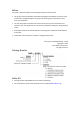


Table Of Contents
- Chapter 1: Safety Information
- Chapter 2: Introduction
- Chapter 3: Installation
- 3.1. Before You Begin
- 3.2. Unpacking the Drive Components
- 3.3. Assembling the Heatsink
- 3.4. Mounting the Bassoon
- 3.5. Connecting the Cables
- 3.5.1. Wiring the Bassoon
- 3.5.2. Connecting the Power Cables
- 3.5.3. Connecting the Auxiliary Power Cable (J4)
- 3.5.4. Feedback and Control Cable Assemblies
- 3.5.5. Main Feedback Cable (Port J3)
- 3.5.6. Main and Auxiliary Feedback Combinations
- 3.5.6.1. Main Encoder Buffered Outputs or Emulated Encoder Outputs Option on Feedback B (J2) (YA[4]=4)
- 3.5.6.2. Differential Auxiliary Encoder Input Option on Feedback B (J2) (YA[4]=2)
- 3.5.6.3. Single-Ended Auxiliary Input Option on Feedback B (J2) (YA[4]=2)
- 3.5.6.4. Pulse-and-Direction Input Option on FEEDBACK B (J2) (YA[4]=0)
- 3.5.7. I/O Cables
- 3.5.8. Communication Cable (Port J1, J8, J9)
- 3.6. Powering Up
- 3.7. Initializing the System
- Chapter 4: Technical Specifications
Bassoon Installation Guide Safety Information
MAN-BASIG (Ver. 1.502)
www.elmomc.com
9
1.1. Warnings
• To avoid electric arcing and hazards to personnel and electrical contacts, never
connect/disconnect the servo drive while the power source is on.
• Power cables can carry a high voltage, even when the motor is not in motion. Disconnect
the Bassoon from all voltage sources before it is opened for servicing.
• The Bassoon servo drive contains grounding conduits for electric current protection. Any
disruption to these conduits may cause the device to become “hot” (live) and dangerous.
• After shutting off the power and removing the power source from your equipment, wait at
least 1 minute before touching or disconnecting parts of the equipment that are normally
loaded with electrical charges (such as capacitors or contacts). Measuring the electrical
contact points with a meter before touching the equipment is recommended.
1.2. Cautions
• The Bassoon servo drive contains hot surfaces and electrically charged components during
operation.
• The maximum AC power supply connected to the instrument must comply with the
parameters outlined in this guide.
• The Bassoon drive must be connected to an approved 24 VDC auxiliary power supply
through a line that is separated from hazardous line voltages using reinforced or double
insulation in accordance with approved safety standards.
• The Bassoon X/230 series is designed to gets its power from a 30 to 255 VAC single phase
power source. It can be connected directly to the line voltage. An isolation transformer is
not needed.
• Before switching on the Bassoon, verify that all safety precautions have been observed and
that the installation procedures in this manual have been followed.
• Do not clean any of the Bassoon drive's soldering with solvent cleaning fluids of pH greater
than 7 (8 to 14). The solvent corrodes the plastic cover causing cracks and eventual damage
to the drive's PCBs.
Elmo recommends using the cleaning fluid Vigon-EFM which is pH Neutral (7).
For further technical information on this recommended cleaning fluid, select the link:
http://www.zestron.com/fileadmin/zestron.com-usa/daten/electronics/Product_TI1s/TI1-
VIGON_EFM-US.pdf