
Manual


Table Of Contents
- Chapter 1: Safety Information
- Chapter 2: Introduction
- Chapter 3: Installation
- 3.1. Before You Begin
- 3.2. Unpacking the Drive Components
- 3.3. Assembling the Heatsink
- 3.4. Mounting the Bassoon
- 3.5. Connecting the Cables
- 3.5.1. Wiring the Bassoon
- 3.5.2. Connecting the Power Cables
- 3.5.3. Connecting the Auxiliary Power Cable (J4)
- 3.5.4. Feedback and Control Cable Assemblies
- 3.5.5. Main Feedback Cable (Port J3)
- 3.5.6. Main and Auxiliary Feedback Combinations
- 3.5.6.1. Main Encoder Buffered Outputs or Emulated Encoder Outputs Option on Feedback B (J2) (YA[4]=4)
- 3.5.6.2. Differential Auxiliary Encoder Input Option on Feedback B (J2) (YA[4]=2)
- 3.5.6.3. Single-Ended Auxiliary Input Option on Feedback B (J2) (YA[4]=2)
- 3.5.6.4. Pulse-and-Direction Input Option on FEEDBACK B (J2) (YA[4]=0)
- 3.5.7. I/O Cables
- 3.5.8. Communication Cable (Port J1, J8, J9)
- 3.6. Powering Up
- 3.7. Initializing the System
- Chapter 4: Technical Specifications
Bassoon Installation Guide Technical Specifications
MAN-BASIG (Ver. 1.502)
www.elmomc.com
66
4.10. Pulse-Width Modulation (PWM)
Feature Details
PWM resolution 12-bit
PWM switching frequency on the load 2/ Ts (factory default 22 kHz on the motor)
4.11. Heat Sink Specifications
The following table indicates the RMS output power when operating the Bassoon at nominal
DC bus voltage:
Bassoon 1/230 3/230 6/230
RMS output power without heat sink (%)
80
40 20
If the input voltage is lower, the RMS output current without a heatsink is higher.
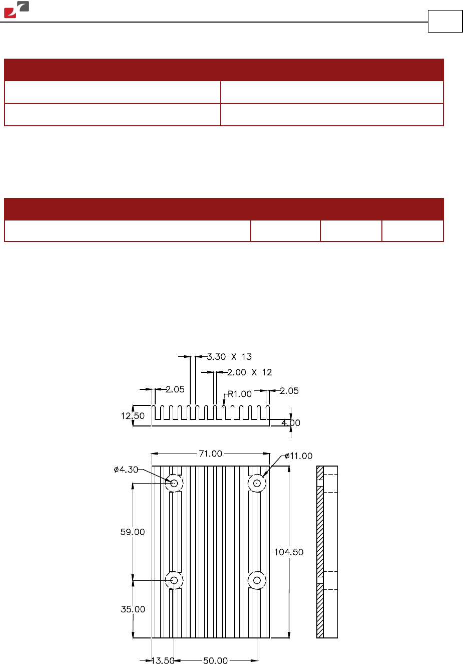
Two types of heat sinks are recommended for ensuring maximum continuous output power of
the drive:
• Finned heat sink
• L-Shaped heat sink
BAS_FIN_HS
Figure 34: Fin-Type Heat Sink Dimensions