
Manual

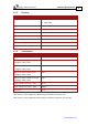


Table Of Contents
- Chapter 1: Safety Information
- Chapter 2: Introduction
- Chapter 3: Installation
- 3.1. Before You Begin
- 3.2. Unpacking the Drive Components
- 3.3. Assembling the Heatsink
- 3.4. Mounting the Bassoon
- 3.5. Connecting the Cables
- 3.5.1. Wiring the Bassoon
- 3.5.2. Connecting the Power Cables
- 3.5.3. Connecting the Auxiliary Power Cable (J4)
- 3.5.4. Feedback and Control Cable Assemblies
- 3.5.5. Main Feedback Cable (Port J3)
- 3.5.6. Main and Auxiliary Feedback Combinations
- 3.5.6.1. Main Encoder Buffered Outputs or Emulated Encoder Outputs Option on Feedback B (J2) (YA[4]=4)
- 3.5.6.2. Differential Auxiliary Encoder Input Option on Feedback B (J2) (YA[4]=2)
- 3.5.6.3. Single-Ended Auxiliary Input Option on Feedback B (J2) (YA[4]=2)
- 3.5.6.4. Pulse-and-Direction Input Option on FEEDBACK B (J2) (YA[4]=0)
- 3.5.7. I/O Cables
- 3.5.8. Communication Cable (Port J1, J8, J9)
- 3.6. Powering Up
- 3.7. Initializing the System
- Chapter 4: Technical Specifications
Bassoon Installation Guide Technical Specifications
MAN-BASIG (Ver. 1.502)
www.elmomc.com
65
4.8.3. Analog Input (J7)
Feature Details Connector Location
Maximum operating differential mode
voltage
±10 V
Maximum absolute differential input
voltage
±16 V
Differential input resistance 3 kΩ
Analog input command resolution 14-bit inputs
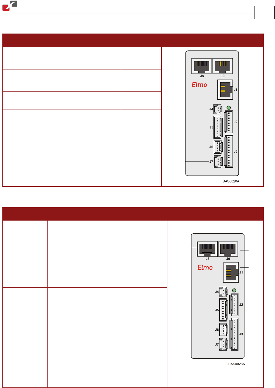
4.9. Communications
Specification Details Connector Location
RS-232 Signals:
• RxD , TxD , Gnd
• Full duplex, serial communication for
setup and control.
• Baud Rate of 9,600 to 115,200
bits/sec.
CAN CAN bus Signals:
• CAN_H, CAN_L, CAN_GND
• Maximum Baud Rate of 1 Mbits/sec.
Version:
• DS 301 V4.01
Device Profile (drive and motion control):
• DS 402
CAN
CAN
RS-232
Analog
Input