
Manual


Table Of Contents
- Chapter 1: Safety Information
- Chapter 2: Introduction
- Chapter 3: Installation
- 3.1. Before You Begin
- 3.2. Unpacking the Drive Components
- 3.3. Assembling the Heatsink
- 3.4. Mounting the Bassoon
- 3.5. Connecting the Cables
- 3.5.1. Wiring the Bassoon
- 3.5.2. Connecting the Power Cables
- 3.5.3. Connecting the Auxiliary Power Cable (J4)
- 3.5.4. Feedback and Control Cable Assemblies
- 3.5.5. Main Feedback Cable (Port J3)
- 3.5.6. Main and Auxiliary Feedback Combinations
- 3.5.6.1. Main Encoder Buffered Outputs or Emulated Encoder Outputs Option on Feedback B (J2) (YA[4]=4)
- 3.5.6.2. Differential Auxiliary Encoder Input Option on Feedback B (J2) (YA[4]=2)
- 3.5.6.3. Single-Ended Auxiliary Input Option on Feedback B (J2) (YA[4]=2)
- 3.5.6.4. Pulse-and-Direction Input Option on FEEDBACK B (J2) (YA[4]=0)
- 3.5.7. I/O Cables
- 3.5.8. Communication Cable (Port J1, J8, J9)
- 3.6. Powering Up
- 3.7. Initializing the System
- Chapter 4: Technical Specifications
Bassoon Installation Guide Technical Specifications
MAN-BASIG (Ver. 1.502)
www.elmomc.com
56
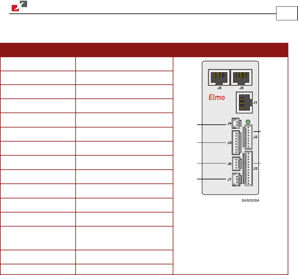
4.4.2. Control and Feedback Connector Specifications
Feature Details Connector Location
Product name Sherlock
Manufacturer Molex
Wire size 24, 26, 28, 30 AWG
Maximum current 2 A
Temperature range
-40° to 105° C (-40° to 221° F)
Plating contact Tin/Lead (Sn/Pb)
Maximum voltage 125 V
Contact resistance
< 20 mΩ
Withstanding voltage 500 VAC
Insulation resistance
> 1000 MΩ
Terminal contact Phosphor bronze
UL files E29179, UL 94 V-0
Cable connector Molex 35507-XX00, where XX is
the number of leads
Hand crimper Molex 63811-1200
Crimp terminal Molex 50212
Auxiliary
Power
supply
Digital
Output
Analog
Input
Digital
Input
Auxiliary
Feedback
Main
Feedback