
Manual


Table Of Contents
- Chapter 1: Safety Information
- Chapter 2: Introduction
- Chapter 3: Installation
- 3.1. Before You Begin
- 3.2. Unpacking the Drive Components
- 3.3. Assembling the Heatsink
- 3.4. Mounting the Bassoon
- 3.5. Connecting the Cables
- 3.5.1. Wiring the Bassoon
- 3.5.2. Connecting the Power Cables
- 3.5.3. Connecting the Auxiliary Power Cable (J4)
- 3.5.4. Feedback and Control Cable Assemblies
- 3.5.5. Main Feedback Cable (Port J3)
- 3.5.6. Main and Auxiliary Feedback Combinations
- 3.5.6.1. Main Encoder Buffered Outputs or Emulated Encoder Outputs Option on Feedback B (J2) (YA[4]=4)
- 3.5.6.2. Differential Auxiliary Encoder Input Option on Feedback B (J2) (YA[4]=2)
- 3.5.6.3. Single-Ended Auxiliary Input Option on Feedback B (J2) (YA[4]=2)
- 3.5.6.4. Pulse-and-Direction Input Option on FEEDBACK B (J2) (YA[4]=0)
- 3.5.7. I/O Cables
- 3.5.8. Communication Cable (Port J1, J8, J9)
- 3.6. Powering Up
- 3.7. Initializing the System
- Chapter 4: Technical Specifications
Bassoon Installation Guide Technical Specifications
MAN-BASIG (Ver. 1.502)
www.elmomc.com
55
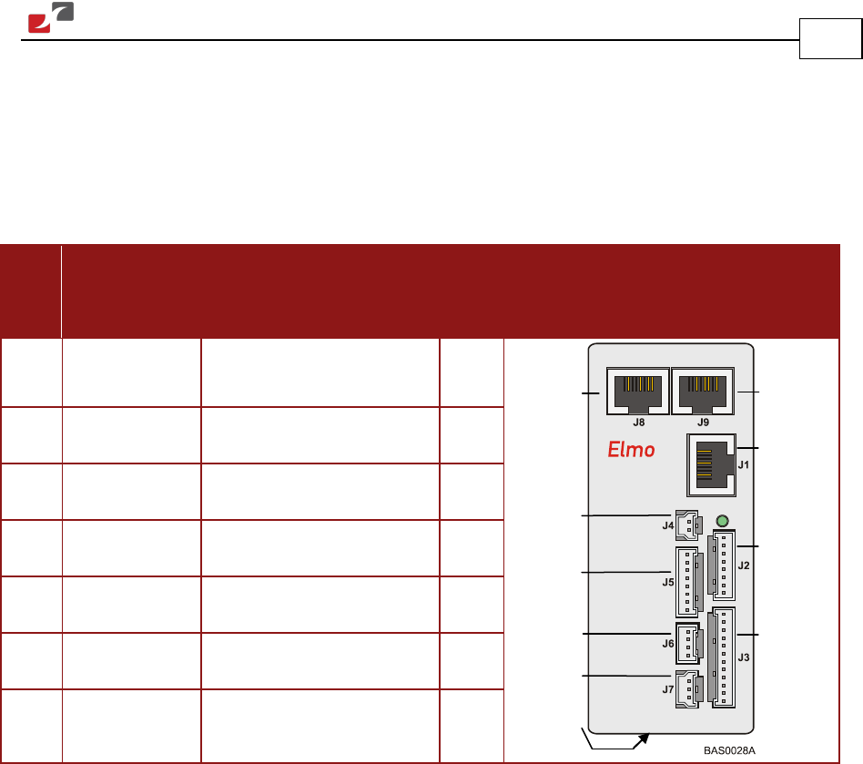
4.4. Bassoon Connectors
The following connectors are used for wiring the Bassoon.
4.4.1. Connector Types
The table below shows the connector panel of the Bassoon.
Pins Type Connector Maker & No.
/
Mating Plug (on Cable)
Port Connector Location
8 RJ-45
RJ-45 jack
mates with RJ-45 plug
J1,
J8, J9
8 2 mm Pitch Molex 35363-0800
mates with 35507-0800
J2, J5
12 2 mm Pitch Molex 35363-1200
mates with 35507-1200
J3
2 2 mm Pitch Molex 35363-0200
mates with 35507-0200
J4
4 2 mm Pitch Molex 35363-0400
mates with 35507-0400
J6
3 2 mm Pitch Molex 35363-0300
mates with 35507-0300
J7
7 5.08 mm Pitch
Terminal Block
Phoenix MSTBA 2.5/7-G-5.08
with MSTB 2.5/7-ST-5.08
power
Auxiliary
Powe
r
Supply
Auxiliary
Feedback
Main
Feedback
Main
Power
CANopen
RS232
Digital
Input
Digital
Output
Analog
Input
CANopen