
Manual

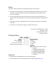


Table Of Contents
- Chapter 1: Safety Information
- Chapter 2: Introduction
- Chapter 3: Installation
- 3.1. Before You Begin
- 3.2. Unpacking the Drive Components
- 3.3. Assembling the Heatsink
- 3.4. Mounting the Bassoon
- 3.5. Connecting the Cables
- 3.5.1. Wiring the Bassoon
- 3.5.2. Connecting the Power Cables
- 3.5.3. Connecting the Auxiliary Power Cable (J4)
- 3.5.4. Feedback and Control Cable Assemblies
- 3.5.5. Main Feedback Cable (Port J3)
- 3.5.6. Main and Auxiliary Feedback Combinations
- 3.5.6.1. Main Encoder Buffered Outputs or Emulated Encoder Outputs Option on Feedback B (J2) (YA[4]=4)
- 3.5.6.2. Differential Auxiliary Encoder Input Option on Feedback B (J2) (YA[4]=2)
- 3.5.6.3. Single-Ended Auxiliary Input Option on Feedback B (J2) (YA[4]=2)
- 3.5.6.4. Pulse-and-Direction Input Option on FEEDBACK B (J2) (YA[4]=0)
- 3.5.7. I/O Cables
- 3.5.8. Communication Cable (Port J1, J8, J9)
- 3.6. Powering Up
- 3.7. Initializing the System
- Chapter 4: Technical Specifications

Bassoon Installation Guide
MAN-BASIG (Ver. 1.502)
5
Table of Contents
Chapter 1: Safety Information ...................................................................................... 8
1.1. Warnings .....................................................................................................................9
1.2. Cautions ......................................................................................................................9
1.3. Directives and Standards ......................................................................................... 10
1.4. CE Marking Conformance ........................................................................................ 10
1.5. Warranty Information ............................................................................................. 10
Chapter 2: Introduction ............................................................................................. 11
2.1. Drive Description ..................................................................................................... 11
2.2. Product Features ..................................................................................................... 11
2.2.1. Current Control ......................................................................................... 11
2.2.2. Velocity Control ........................................................................................ 11
2.2.3. Position Control ........................................................................................ 12
2.2.4. Advanced Position Control (Advanced model only) ................................. 12
2.2.5. Communication Options ........................................................................... 12
2.2.6. Feedback Options ..................................................................................... 12
2.2.7. Fault Protection ........................................................................................ 13
2.3. System Architecture ................................................................................................ 13
2.4. How to Use this Guide ............................................................................................. 14
Chapter 3: Installation ............................................................................................... 15
3.1. Before You Begin ..................................................................................................... 15
3.1.1. Site Requirements .................................................................................... 15
3.1.2. Hardware Requirements .......................................................................... 15
3.1.3. AC Power Requirements ........................................................................... 17
3.2. Unpacking the Drive Components ........................................................................... 17
3.3. Assembling the Heatsink ......................................................................................... 18
3.4. Mounting the Bassoon ............................................................................................ 18
3.4.1. Mounting on a DIN Rail ............................................................................. 18
3.4.2. Mounting Directly onto a Wall ................................................................. 19
3.5. Connecting the Cables ............................................................................................. 20
3.5.1. Wiring the Bassoon ................................................................................... 20
3.5.2. Connecting the Power Cables ................................................................... 23
3.5.2.1. Connecting the Motor Cable ................................................... 23
3.5.2.2. Connecting the Main Power Cable .......................................... 24
3.5.3. Connecting the Auxiliary Power Cable (J4) ............................................... 25
3.5.4. Feedback and Control Cable Assemblies .................................................. 26
3.5.5. Main Feedback Cable (Port J3) ................................................................. 27
3.5.6. Main and Auxiliary Feedback Combinations ............................................ 34
3.5.6.1. Main Encoder Buffered Outputs or Emulated Encoder Outputs
Option on Feedback B (J2) (YA[4]=4) ....................................... 35