
Manual

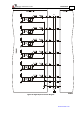


Table Of Contents
- Chapter 1: Safety Information
- Chapter 2: Introduction
- Chapter 3: Installation
- 3.1. Before You Begin
- 3.2. Unpacking the Drive Components
- 3.3. Assembling the Heatsink
- 3.4. Mounting the Bassoon
- 3.5. Connecting the Cables
- 3.5.1. Wiring the Bassoon
- 3.5.2. Connecting the Power Cables
- 3.5.3. Connecting the Auxiliary Power Cable (J4)
- 3.5.4. Feedback and Control Cable Assemblies
- 3.5.5. Main Feedback Cable (Port J3)
- 3.5.6. Main and Auxiliary Feedback Combinations
- 3.5.6.1. Main Encoder Buffered Outputs or Emulated Encoder Outputs Option on Feedback B (J2) (YA[4]=4)
- 3.5.6.2. Differential Auxiliary Encoder Input Option on Feedback B (J2) (YA[4]=2)
- 3.5.6.3. Single-Ended Auxiliary Input Option on Feedback B (J2) (YA[4]=2)
- 3.5.6.4. Pulse-and-Direction Input Option on FEEDBACK B (J2) (YA[4]=0)
- 3.5.7. I/O Cables
- 3.5.8. Communication Cable (Port J1, J8, J9)
- 3.6. Powering Up
- 3.7. Initializing the System
- Chapter 4: Technical Specifications
Bassoon Installation Guide Installation
MAN-BASIG (Ver. 1.502)
www.elmomc.com
48
3.6. Powering Up
After the Bassoon has been mounted, check that the cables are intact. The Bassoon servo drive
is then ready to be powered up.
Caution:
Before applying power, ensure that the AC supply is within the range specified
for your specific type of Bassoon.
To power up the system, first switch on the auxiliary power and then the main power supply.
(Note that this order is recommended but not critical; if a problem occurs, the system is well
protected.) The two-color LED turns green to indicate proper functioning.
3.7. Initializing the System
After the Bassoon has been connected and mounted, the system must be set up and initialized.
This is accomplished using the Composer, Elmo’s Windows-based software application. Install
the application and then perform setup and initialization according to the directions in the
Composer Software Manual.