
Manual

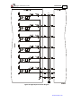


Table Of Contents
- Chapter 1: Safety Information
- Chapter 2: Introduction
- Chapter 3: Installation
- 3.1. Before You Begin
- 3.2. Unpacking the Drive Components
- 3.3. Assembling the Heatsink
- 3.4. Mounting the Bassoon
- 3.5. Connecting the Cables
- 3.5.1. Wiring the Bassoon
- 3.5.2. Connecting the Power Cables
- 3.5.3. Connecting the Auxiliary Power Cable (J4)
- 3.5.4. Feedback and Control Cable Assemblies
- 3.5.5. Main Feedback Cable (Port J3)
- 3.5.6. Main and Auxiliary Feedback Combinations
- 3.5.6.1. Main Encoder Buffered Outputs or Emulated Encoder Outputs Option on Feedback B (J2) (YA[4]=4)
- 3.5.6.2. Differential Auxiliary Encoder Input Option on Feedback B (J2) (YA[4]=2)
- 3.5.6.3. Single-Ended Auxiliary Input Option on Feedback B (J2) (YA[4]=2)
- 3.5.6.4. Pulse-and-Direction Input Option on FEEDBACK B (J2) (YA[4]=0)
- 3.5.7. I/O Cables
- 3.5.8. Communication Cable (Port J1, J8, J9)
- 3.6. Powering Up
- 3.7. Initializing the System
- Chapter 4: Technical Specifications
Bassoon Installation Guide Installation
MAN-BASIG (Ver. 1.502)
www.elmomc.com
46
Figure 29: RS-232 Connection Diagram
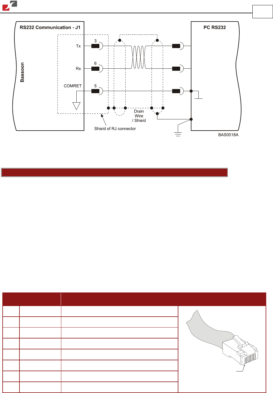
3.5.8.2. CANopen Communication
Notes for connecting the CANopen communication cable (J8 and/or J9 port):
• Use a 26 or 28 AWG twisted pair shielded cable. The cable should have an aluminum foil
shield covered by copper braid with a drain wire.
• Connect the shield to the ground of the host (PC). Usually, this connection is soldered
internally inside the connector at the PC end. You can use the drain wire or shield to
facilitate connection.
• The male RJ plug must have a shield cover.
• Ensure that the shield of the cable is connected to the shield of the RJ plug. The drain wire
can be used to facilitate the connection.
• Connect a termination 120-Ω resistor at each of the two ends of the network cable.
Pin Signal Function Pin Positions
1 CAN_H CAN_H busline (dominant high)
1
2 CAN_L CAN_L busline (dominant low)
3 CAN_GND CAN ground
4 — —
5 — —
6 CAN_SHLD Shield, connected to the RJ plug cover
7 CAN_GND CAN ground
8 — —
Table 16: CANopen (J8, J9) Cable Pin Assignments