
Manual


Table Of Contents
- Chapter 1: Safety Information
- Chapter 2: Introduction
- Chapter 3: Installation
- 3.1. Before You Begin
- 3.2. Unpacking the Drive Components
- 3.3. Assembling the Heatsink
- 3.4. Mounting the Bassoon
- 3.5. Connecting the Cables
- 3.5.1. Wiring the Bassoon
- 3.5.2. Connecting the Power Cables
- 3.5.3. Connecting the Auxiliary Power Cable (J4)
- 3.5.4. Feedback and Control Cable Assemblies
- 3.5.5. Main Feedback Cable (Port J3)
- 3.5.6. Main and Auxiliary Feedback Combinations
- 3.5.6.1. Main Encoder Buffered Outputs or Emulated Encoder Outputs Option on Feedback B (J2) (YA[4]=4)
- 3.5.6.2. Differential Auxiliary Encoder Input Option on Feedback B (J2) (YA[4]=2)
- 3.5.6.3. Single-Ended Auxiliary Input Option on Feedback B (J2) (YA[4]=2)
- 3.5.6.4. Pulse-and-Direction Input Option on FEEDBACK B (J2) (YA[4]=0)
- 3.5.7. I/O Cables
- 3.5.8. Communication Cable (Port J1, J8, J9)
- 3.6. Powering Up
- 3.7. Initializing the System
- Chapter 4: Technical Specifications
Bassoon Installation Guide Installation
MAN-BASIG (Ver. 1.502)
www.elmomc.com
41
3.5.7. I/O Cables
The following table lists the I/O cables that you should connect according to your specific
requirements:
I/O Description Total Port
Digital input 6 J5
Digital output 2 J6
Analog input 1 J7
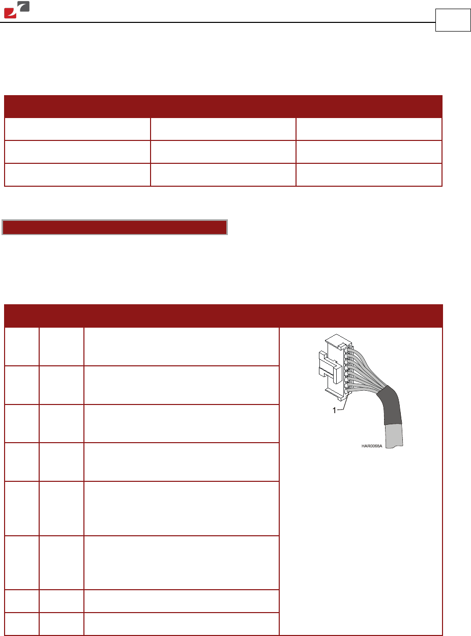
3.5.7.1. Digital Input (Port J5)
Notes for connecting the digital input cable:
• Use 24 or 26 AWG twisted pair shielded cable.
• Connect the cable shield to the ground near the signal source (controller) according to the
manufacturer’s recommendations.
Pin Signal Function Pin Positions
1 IN1 Programmable input 1
(general purpose, RLS, FLS, INH)
2 IN2 Programmable input 2
(general purpose, RLS, FLS, INH)
3 IN3 Programmable input 3
(general purpose, RLS, FLS, INH)
4 IN4 Programmable input 4
(general purpose, RLS, FLS, INH)
5 IN5 Programmable input 5
(event capture, Main Home,
general purpose, RLS, FLS, INH)
6 IN6 Programmable input 6
(event capture, Auxiliary Home,
general purpose, RLS, FLS, INH)
7 INRET Programmable input return
8 INRET Programmable input return
Table 12: Digital Input Cable Pin Assignments