
Manual
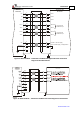


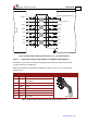

Table Of Contents
- Chapter 1: Safety Information
- Chapter 2: Introduction
- Chapter 3: Installation
- 3.1. Before You Begin
- 3.2. Unpacking the Drive Components
- 3.3. Assembling the Heatsink
- 3.4. Mounting the Bassoon
- 3.5. Connecting the Cables
- 3.5.1. Wiring the Bassoon
- 3.5.2. Connecting the Power Cables
- 3.5.3. Connecting the Auxiliary Power Cable (J4)
- 3.5.4. Feedback and Control Cable Assemblies
- 3.5.5. Main Feedback Cable (Port J3)
- 3.5.6. Main and Auxiliary Feedback Combinations
- 3.5.6.1. Main Encoder Buffered Outputs or Emulated Encoder Outputs Option on Feedback B (J2) (YA[4]=4)
- 3.5.6.2. Differential Auxiliary Encoder Input Option on Feedback B (J2) (YA[4]=2)
- 3.5.6.3. Single-Ended Auxiliary Input Option on Feedback B (J2) (YA[4]=2)
- 3.5.6.4. Pulse-and-Direction Input Option on FEEDBACK B (J2) (YA[4]=0)
- 3.5.7. I/O Cables
- 3.5.8. Communication Cable (Port J1, J8, J9)
- 3.6. Powering Up
- 3.7. Initializing the System
- Chapter 4: Technical Specifications
Bassoon Installation Guide Installation
MAN-BASIG (Ver. 1.502)
www.elmomc.com
39
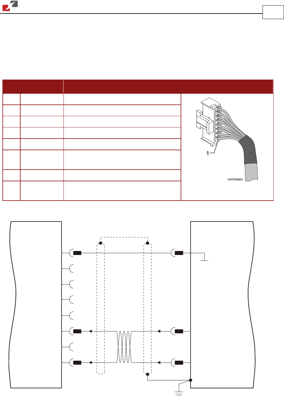
3.5.6.4. Pulse-and-Direction Input Option on FEEDBACK B (J2) (YA[4]=0)
This mode is used for input of differential or single-ended pulse-and-direction position
commands.
Below are the signals on the Auxiliary Feedback ports when set up to run as a single-ended
pulse-and-direction input:
Pin Signal Function Pin Positions
1 SUPRET Supply return
2 +5 V NA
3 — —
4 — —
5 — —
6 DIR/CHB Direction input (push/pull 5 V or
open collector)
7 — —
8 PULS/CHA Pulse input (push/pull 5 V or open
collector)
Table 10: Pulse-and-Direction Auxiliary Encoder Pin Assignments on J2
1
3
6
7
8
Controller
Feedback B - J2
SUPRET
DIR / CHB
PULS / CHA
2
Supply Voltage Return
BAS0026A
Bassoon
DIRECTION
PULSE
5
1
4
Figure 24: Pulse-and-Direction Auxiliary Encoder Pins on J2 - Connection Diagram