
Manual
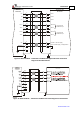


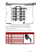

Table Of Contents
- Chapter 1: Safety Information
- Chapter 2: Introduction
- Chapter 3: Installation
- 3.1. Before You Begin
- 3.2. Unpacking the Drive Components
- 3.3. Assembling the Heatsink
- 3.4. Mounting the Bassoon
- 3.5. Connecting the Cables
- 3.5.1. Wiring the Bassoon
- 3.5.2. Connecting the Power Cables
- 3.5.3. Connecting the Auxiliary Power Cable (J4)
- 3.5.4. Feedback and Control Cable Assemblies
- 3.5.5. Main Feedback Cable (Port J3)
- 3.5.6. Main and Auxiliary Feedback Combinations
- 3.5.6.1. Main Encoder Buffered Outputs or Emulated Encoder Outputs Option on Feedback B (J2) (YA[4]=4)
- 3.5.6.2. Differential Auxiliary Encoder Input Option on Feedback B (J2) (YA[4]=2)
- 3.5.6.3. Single-Ended Auxiliary Input Option on Feedback B (J2) (YA[4]=2)
- 3.5.6.4. Pulse-and-Direction Input Option on FEEDBACK B (J2) (YA[4]=0)
- 3.5.7. I/O Cables
- 3.5.8. Communication Cable (Port J1, J8, J9)
- 3.6. Powering Up
- 3.7. Initializing the System
- Chapter 4: Technical Specifications
Bassoon Installation Guide Installation
MAN-BASIG (Ver. 1.502)
www.elmomc.com
36
1
3
4
5
6
7
8
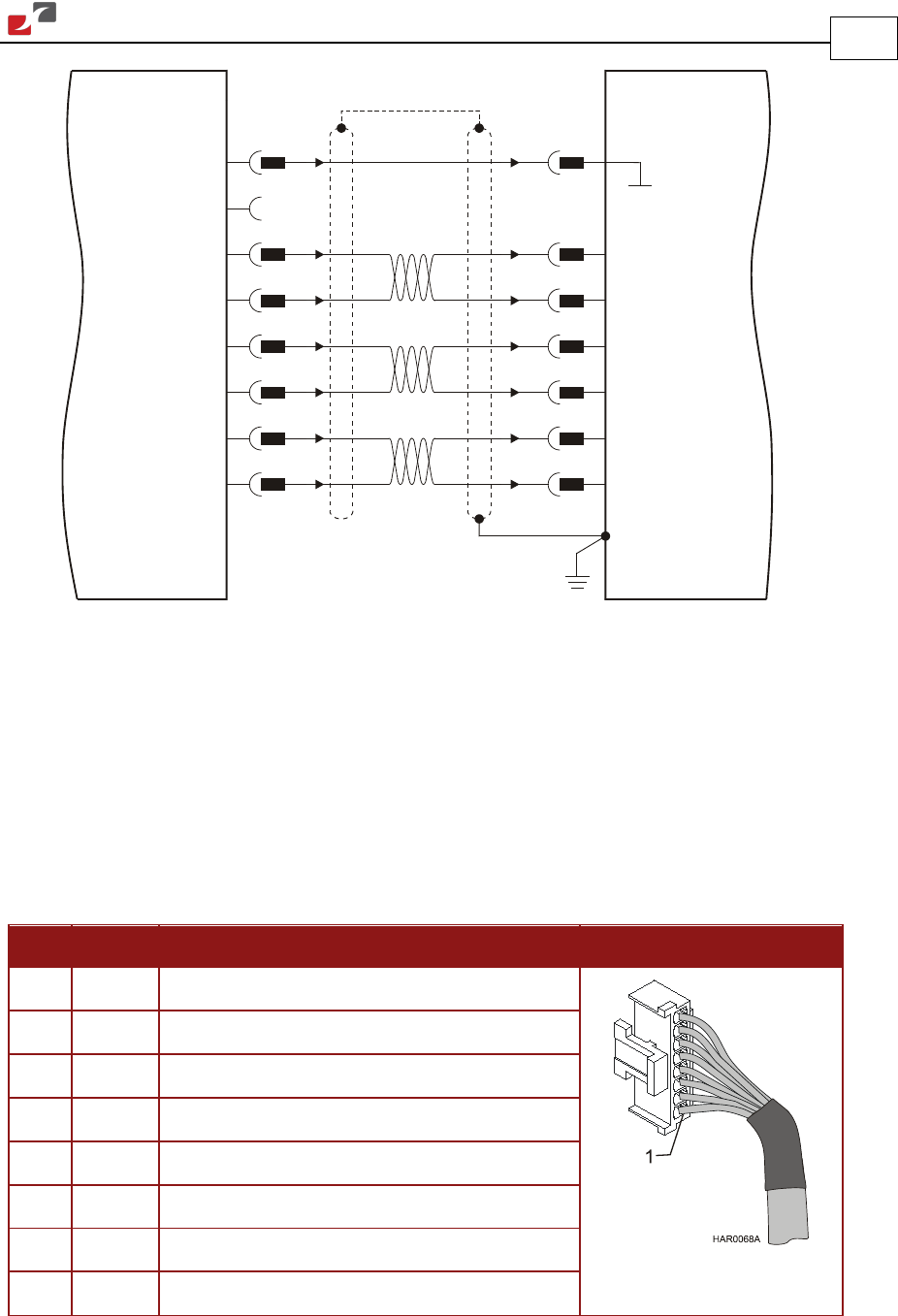
Feedback B - J2
SUPRET
+5v
INDEXO-
INDEXO
CHBO-
CHBO
CHAO-
CHAO
2
INDEX-
INDEX
CHB-
CHB
CHA-
CHA
Controller
Bassoon
BAS0023A
Figure 21: Main Encoder Buffered Output or Emulated Encoder Output on J2 - Connection
Diagram
3.5.6.2. Differential Auxiliary Encoder Input Option on Feedback B (J2) (YA[4]=2)
The Bassoon can be used as a slave by receiving the position (on Port B) of the master encoder
data in Follower or ECAM mode.
Below are the signals on the Auxiliary Feedback port when set up to run as a differential
auxiliary encoder input:
Pin Signal Function Pin Positions
1 SUPRET Supply return
2 +5 V Encoder + 5 V supply voltage, 5 V @ 200 mA
3 INDEX- Auxiliary index low input
4 INDEX Auxiliary index high input
5 CHB- Auxiliary channel B low input
6 CHB Auxiliary channel B high input
7 CHA- Auxiliary channel A low input
8 CHA Auxiliary channel A high input
Table 8: Differential Auxiliary Encoder Input Pin Assignments on J2