
Manual
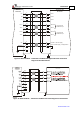


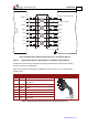

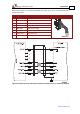
Table Of Contents
- Chapter 1: Safety Information
- Chapter 2: Introduction
- Chapter 3: Installation
- 3.1. Before You Begin
- 3.2. Unpacking the Drive Components
- 3.3. Assembling the Heatsink
- 3.4. Mounting the Bassoon
- 3.5. Connecting the Cables
- 3.5.1. Wiring the Bassoon
- 3.5.2. Connecting the Power Cables
- 3.5.3. Connecting the Auxiliary Power Cable (J4)
- 3.5.4. Feedback and Control Cable Assemblies
- 3.5.5. Main Feedback Cable (Port J3)
- 3.5.6. Main and Auxiliary Feedback Combinations
- 3.5.6.1. Main Encoder Buffered Outputs or Emulated Encoder Outputs Option on Feedback B (J2) (YA[4]=4)
- 3.5.6.2. Differential Auxiliary Encoder Input Option on Feedback B (J2) (YA[4]=2)
- 3.5.6.3. Single-Ended Auxiliary Input Option on Feedback B (J2) (YA[4]=2)
- 3.5.6.4. Pulse-and-Direction Input Option on FEEDBACK B (J2) (YA[4]=0)
- 3.5.7. I/O Cables
- 3.5.8. Communication Cable (Port J1, J8, J9)
- 3.6. Powering Up
- 3.7. Initializing the System
- Chapter 4: Technical Specifications
Bassoon Installation Guide Installation
MAN-BASIG (Ver. 1.502)
www.elmomc.com
31
2
10
9
Bassoon
Feedback A
1
Hall C
Hall B
Tacho+
Tacho-
3
11
Encoder / Hall +5v Supply
Hall / Encoder Supply / Voltage Return
4
HC
HB
Tac2+
Tac2-
Tac1+
Tac1-
+5V
SUPRET
BAS0035A
12
Hall A
HA
6
Tacho+
Tacho-
Up to 20Vmax
Feedback Input
Up to 50Vmax
Feedback Input
Tachometer with
Hall Sensor
5
Figure 15: Main Feedback – Tachometer Feedback with Digital Hall Sensor Connection
Diagram for Brushless Motors
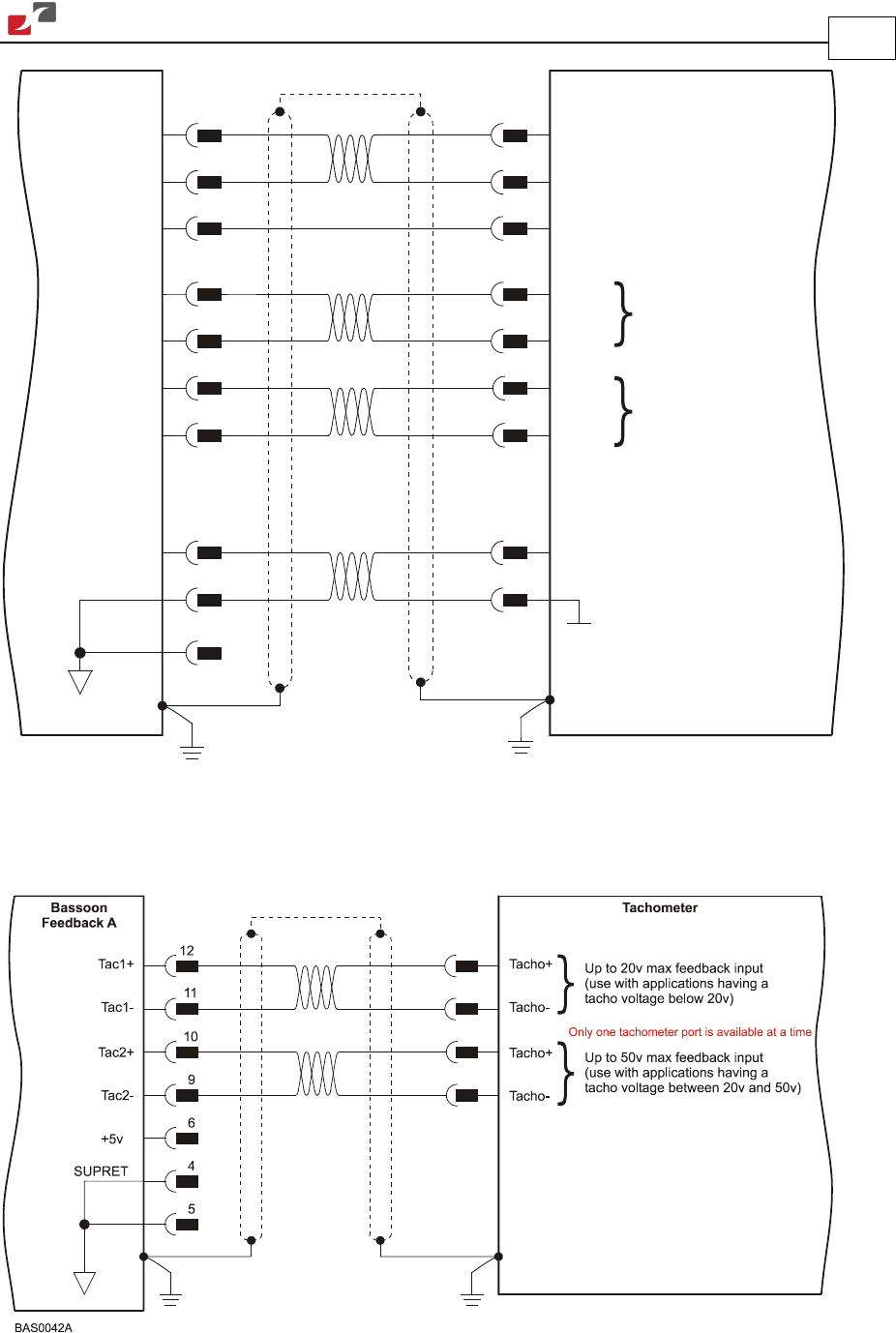
Figure 16: Main Feedback – Tachometer Feedback Connection Diagram for Brush Motors