
Manual

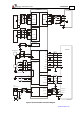

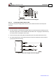


Table Of Contents
- Chapter 1: Safety Information
- Chapter 2: Introduction
- Chapter 3: Installation
- 3.1. Before You Begin
- 3.2. Unpacking the Drive Components
- 3.3. Assembling the Heatsink
- 3.4. Mounting the Bassoon
- 3.5. Connecting the Cables
- 3.5.1. Wiring the Bassoon
- 3.5.2. Connecting the Power Cables
- 3.5.3. Connecting the Auxiliary Power Cable (J4)
- 3.5.4. Feedback and Control Cable Assemblies
- 3.5.5. Main Feedback Cable (Port J3)
- 3.5.6. Main and Auxiliary Feedback Combinations
- 3.5.6.1. Main Encoder Buffered Outputs or Emulated Encoder Outputs Option on Feedback B (J2) (YA[4]=4)
- 3.5.6.2. Differential Auxiliary Encoder Input Option on Feedback B (J2) (YA[4]=2)
- 3.5.6.3. Single-Ended Auxiliary Input Option on Feedback B (J2) (YA[4]=2)
- 3.5.6.4. Pulse-and-Direction Input Option on FEEDBACK B (J2) (YA[4]=0)
- 3.5.7. I/O Cables
- 3.5.8. Communication Cable (Port J1, J8, J9)
- 3.6. Powering Up
- 3.7. Initializing the System
- Chapter 4: Technical Specifications
Bassoon Installation Guide Installation
MAN-BASIG (Ver. 1.502)
www.elmomc.com
29
EnDat (Heidenhain)
Absolute Encoder
Stegmann
Absolute Encoder
4 SUPRET Supply return SUPRET Supply return
5 SUPRET Supply return SUPRET Supply return
6 +5V Encoder
+5 V supply voltage,
5 V @ 200 mA maximum
+8V Encoder
+8 V supply voltage,
8 V @ 90 mA maximum
7 DATA - Data complement DATA - Data complement
8 DATA + DATA DATA + DATA
9 B - Cos B complement B - Cos B complement
10 B + Cos B B + Cos B
11 A - Sine A complement A - Sin A
12 A + Sine A A + Sine A complement
Table 5: Main Feedback Cable Pin Assignments (Part B)
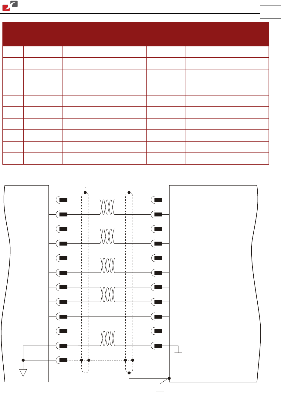
2
10
9
8
7
Incremental Encoder
with Hall Sensor
Bassoon
Feedback A - J3
1
Hall C
Hall B
CHB
CHB-
INDEX
INDEX-
CHA
CHA-
12
11
3
Hall A
6
Encoder / Hall +5v Supply
Hall / Encoder Supply / Voltage Return5
4
HC
HB
CHB
CHB-
INDEX
INDEX-
CHA
CHA-
HA
+5v
SUPRET
SUPRET
BAS0015A
Drain
Wire
/ Shield
Figure 12: Main Feedback- Incremental Encoder Connection Diagram