
Manual


Table Of Contents
- Chapter 1: Safety Information
- Chapter 2: Introduction
- Chapter 3: Installation
- 3.1. Before You Begin
- 3.2. Unpacking the Drive Components
- 3.3. Assembling the Heatsink
- 3.4. Mounting the Bassoon
- 3.5. Connecting the Cables
- 3.5.1. Wiring the Bassoon
- 3.5.2. Connecting the Power Cables
- 3.5.3. Connecting the Auxiliary Power Cable (J4)
- 3.5.4. Feedback and Control Cable Assemblies
- 3.5.5. Main Feedback Cable (Port J3)
- 3.5.6. Main and Auxiliary Feedback Combinations
- 3.5.6.1. Main Encoder Buffered Outputs or Emulated Encoder Outputs Option on Feedback B (J2) (YA[4]=4)
- 3.5.6.2. Differential Auxiliary Encoder Input Option on Feedback B (J2) (YA[4]=2)
- 3.5.6.3. Single-Ended Auxiliary Input Option on Feedback B (J2) (YA[4]=2)
- 3.5.6.4. Pulse-and-Direction Input Option on FEEDBACK B (J2) (YA[4]=0)
- 3.5.7. I/O Cables
- 3.5.8. Communication Cable (Port J1, J8, J9)
- 3.6. Powering Up
- 3.7. Initializing the System
- Chapter 4: Technical Specifications
Bassoon Installation Guide Installation
MAN-BASIG (Ver. 1.502)
www.elmomc.com
27
3.5.5. Main Feedback Cable (Port J3)
The main feedback cable is used to transfer feedback data from the motor to the drive.
The Bassoon accepts the following as a main feedback mechanism:
• Incremental encoder only
• Incremental encoder with digital Hall sensors
• Digital Hall sensors only
• Incremental Analog (Sine/Cosine) encoder (option)
• Resolver (option)
• Tachometer and potentiometer
• Absolute encoder
Connect the main feedback cable from the motor to the J3 port on the front of the Bassoon,
using a 12-pin Molex plug.
Notes:
• Connect the drain wire to pin 4. If the cable has no drain wire, connect the shield to pin 4.
• Ground the shield to the motor chassis.
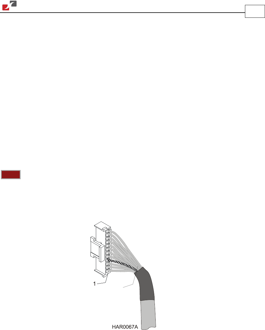
Figure 11: The Main Feedback (J3) Cable
Drain Wire
or Shield