
Manual


Table Of Contents
- Chapter 1: Safety Information
- Chapter 2: Introduction
- Chapter 3: Installation
- 3.1. Before You Begin
- 3.2. Unpacking the Drive Components
- 3.3. Assembling the Heatsink
- 3.4. Mounting the Bassoon
- 3.5. Connecting the Cables
- 3.5.1. Wiring the Bassoon
- 3.5.2. Connecting the Power Cables
- 3.5.3. Connecting the Auxiliary Power Cable (J4)
- 3.5.4. Feedback and Control Cable Assemblies
- 3.5.5. Main Feedback Cable (Port J3)
- 3.5.6. Main and Auxiliary Feedback Combinations
- 3.5.6.1. Main Encoder Buffered Outputs or Emulated Encoder Outputs Option on Feedback B (J2) (YA[4]=4)
- 3.5.6.2. Differential Auxiliary Encoder Input Option on Feedback B (J2) (YA[4]=2)
- 3.5.6.3. Single-Ended Auxiliary Input Option on Feedback B (J2) (YA[4]=2)
- 3.5.6.4. Pulse-and-Direction Input Option on FEEDBACK B (J2) (YA[4]=0)
- 3.5.7. I/O Cables
- 3.5.8. Communication Cable (Port J1, J8, J9)
- 3.6. Powering Up
- 3.7. Initializing the System
- Chapter 4: Technical Specifications
Bassoon Installation Guide Installation
MAN-BASIG (Ver. 1.502)
www.elmomc.com
26
3.5.4. Feedback and Control Cable Assemblies
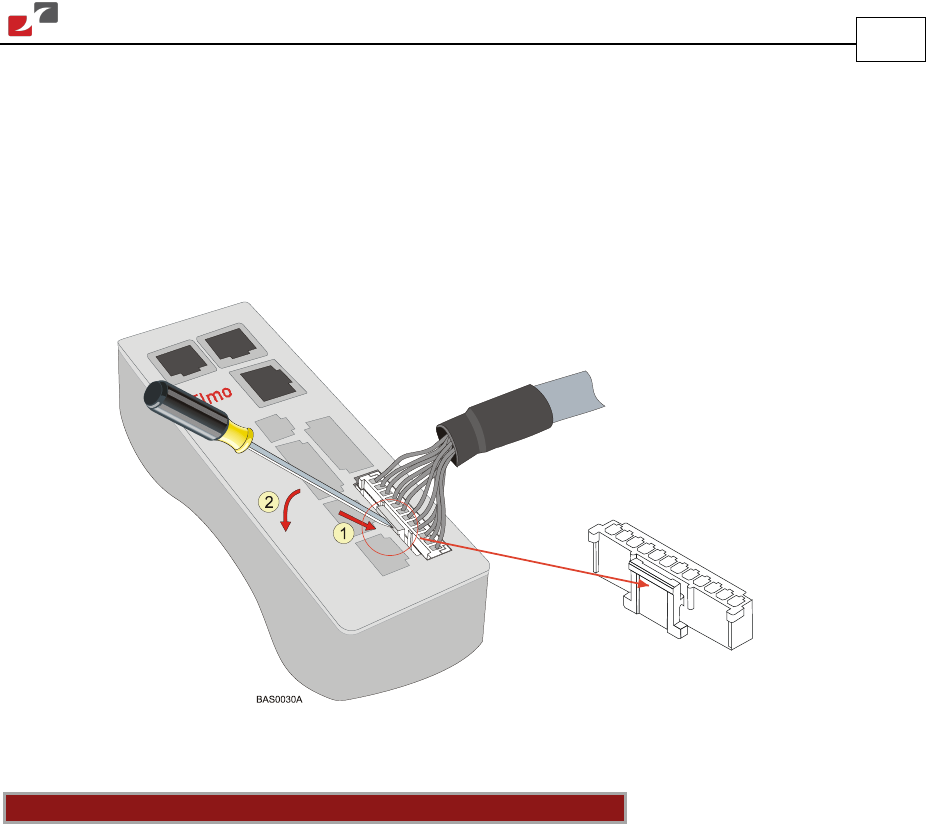
The Auxiliary Power Cable (J4), the Feedback cables (J2 and J3) and the I/O cables (J5, J6 and J7)
all use 2 mm pitch Molex “Sherlock” connectors. These connectors snap together quite easily,
but require a small standard screwdriver for disassembly. To disassemble the Molex connector
simply (1) slip the screwdriver into the lock (this will cause the lock to disengage) and (2) twist
the screwdriver downward with light pressure on the handle (see the figure below).
Figure 10: Disconnecting Molex Connectors
Notes for assembling Feedback and Control cable assemblies:
• Use 24 or 26 AWG twisted-pair shielded cables.
• On the motor side connections, ground the shield to the motor chassis.
• On controller side connections, follow the controller manufacturer’s recommendations
concerning shield and/or drain wire connections.