
Manual

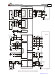

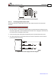


Table Of Contents
- Chapter 1: Safety Information
- Chapter 2: Introduction
- Chapter 3: Installation
- 3.1. Before You Begin
- 3.2. Unpacking the Drive Components
- 3.3. Assembling the Heatsink
- 3.4. Mounting the Bassoon
- 3.5. Connecting the Cables
- 3.5.1. Wiring the Bassoon
- 3.5.2. Connecting the Power Cables
- 3.5.3. Connecting the Auxiliary Power Cable (J4)
- 3.5.4. Feedback and Control Cable Assemblies
- 3.5.5. Main Feedback Cable (Port J3)
- 3.5.6. Main and Auxiliary Feedback Combinations
- 3.5.6.1. Main Encoder Buffered Outputs or Emulated Encoder Outputs Option on Feedback B (J2) (YA[4]=4)
- 3.5.6.2. Differential Auxiliary Encoder Input Option on Feedback B (J2) (YA[4]=2)
- 3.5.6.3. Single-Ended Auxiliary Input Option on Feedback B (J2) (YA[4]=2)
- 3.5.6.4. Pulse-and-Direction Input Option on FEEDBACK B (J2) (YA[4]=0)
- 3.5.7. I/O Cables
- 3.5.8. Communication Cable (Port J1, J8, J9)
- 3.6. Powering Up
- 3.7. Initializing the System
- Chapter 4: Technical Specifications
Bassoon Installation Guide Installation
MAN-BASIG (Ver. 1.502)
www.elmomc.com
25
3.5.3. Connecting the Auxiliary Power Cable (J4)
Connect the auxiliary power supply to the J4 port on the front of the Bassoon, using a
2-pin Molex plug. Remember, you are working with DC power; be sure to exercise caution. The
required voltage is 24 VDC.
Notes for 24 VDC auxiliary power supply connections:
• Use a 24 or 26 AWG twisted pair shielded cable.
• The 24 VDC auxiliary power supply must meet all safety requirements and must be
separated from hazardous live voltages using reinforced or double insulation in accordance
with approved safety standards.
• For safety reasons, connect the return (common) of the 24 VDC source to the closest
ground.
• Connect the cable shield to the closest ground near the 24 VDC source.
• Before applying power, first verify the polarity of the connection.
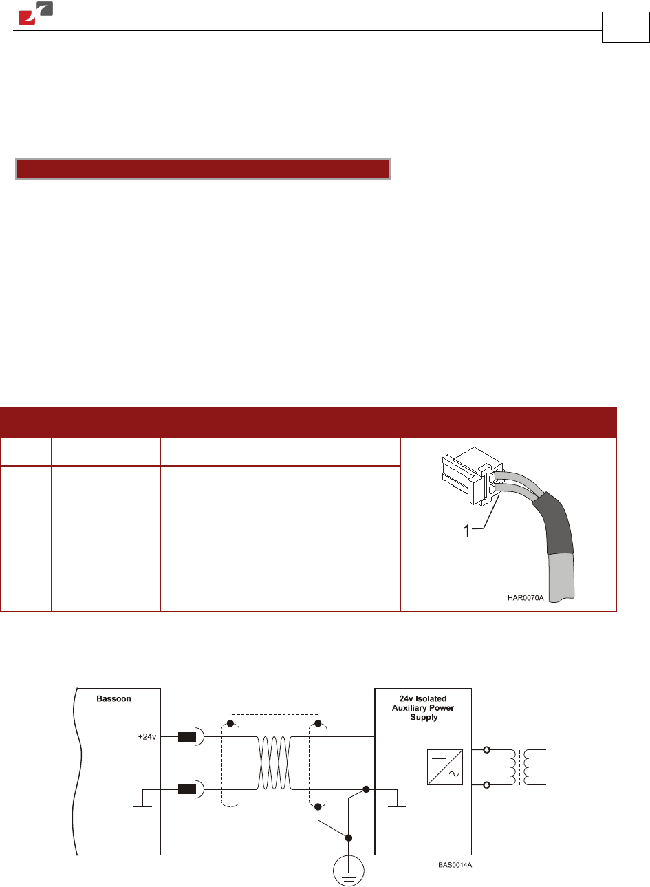
Pin Signal Function Pin Positions
1 +24VDC +24 VDC auxiliary power supply
2 RET24VDC Return (common) of the 24 VDC
auxiliary power supply
Table 3: Auxiliary Power Cable Plug
Figure 9: Auxiliary Power Supply (J4) Connection Diagram