
Manual


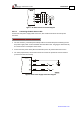


Table Of Contents
- Chapter 1: Safety Information
- Chapter 2: Introduction
- Chapter 3: Installation
- 3.1. Before You Begin
- 3.2. Unpacking the Drive Components
- 3.3. Assembling the Heatsink
- 3.4. Mounting the Bassoon
- 3.5. Connecting the Cables
- 3.5.1. Wiring the Bassoon
- 3.5.2. Connecting the Power Cables
- 3.5.3. Connecting the Auxiliary Power Cable (J4)
- 3.5.4. Feedback and Control Cable Assemblies
- 3.5.5. Main Feedback Cable (Port J3)
- 3.5.6. Main and Auxiliary Feedback Combinations
- 3.5.6.1. Main Encoder Buffered Outputs or Emulated Encoder Outputs Option on Feedback B (J2) (YA[4]=4)
- 3.5.6.2. Differential Auxiliary Encoder Input Option on Feedback B (J2) (YA[4]=2)
- 3.5.6.3. Single-Ended Auxiliary Input Option on Feedback B (J2) (YA[4]=2)
- 3.5.6.4. Pulse-and-Direction Input Option on FEEDBACK B (J2) (YA[4]=0)
- 3.5.7. I/O Cables
- 3.5.8. Communication Cable (Port J1, J8, J9)
- 3.6. Powering Up
- 3.7. Initializing the System
- Chapter 4: Technical Specifications
Bassoon Installation Guide Installation
MAN-BASIG (Ver. 1.502)
www.elmomc.com
24
Figure 7: AC Motor Power Connection Diagram
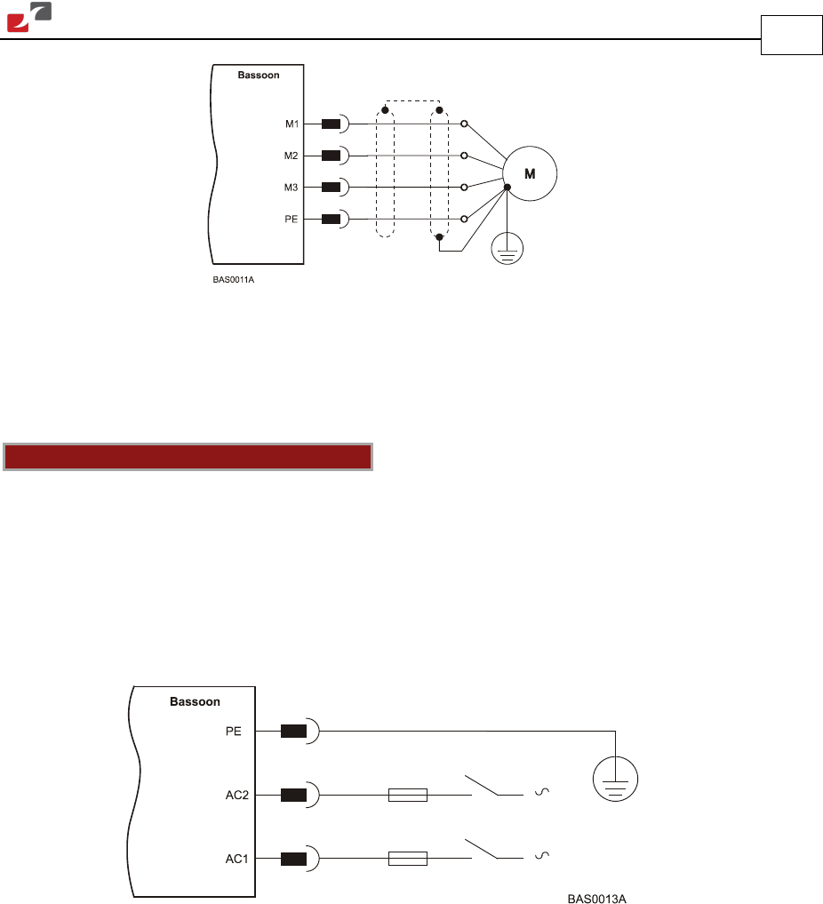
3.5.2.2. Connecting the Main Power Cable
Connect the main power supply cable to the AC1, AC2 and PE terminals of the main power
connector.
Notes for connecting the AC power cable:
• For best immunity, a shielded (not twisted) cable is recommended (not mandatory) for the
AC power supply cable. A 3-wire shielded cable should be used. The gauge is determined by
the actual current consumption of the motor.
• Connect the two power wires (Neutral and Phase) to the AC power leads of the source.
• For safety requirements, the third wire must be used for the protective earth connection
(connected to the PE terminal).
Figure 8: Main Power Supply Connection Diagram