
Manual


Table Of Contents
- Chapter 1: Safety Information
- Chapter 2: Introduction
- Chapter 3: Installation
- 3.1. Before You Begin
- 3.2. Unpacking the Drive Components
- 3.3. Assembling the Heatsink
- 3.4. Mounting the Bassoon
- 3.5. Connecting the Cables
- 3.5.1. Wiring the Bassoon
- 3.5.2. Connecting the Power Cables
- 3.5.3. Connecting the Auxiliary Power Cable (J4)
- 3.5.4. Feedback and Control Cable Assemblies
- 3.5.5. Main Feedback Cable (Port J3)
- 3.5.6. Main and Auxiliary Feedback Combinations
- 3.5.6.1. Main Encoder Buffered Outputs or Emulated Encoder Outputs Option on Feedback B (J2) (YA[4]=4)
- 3.5.6.2. Differential Auxiliary Encoder Input Option on Feedback B (J2) (YA[4]=2)
- 3.5.6.3. Single-Ended Auxiliary Input Option on Feedback B (J2) (YA[4]=2)
- 3.5.6.4. Pulse-and-Direction Input Option on FEEDBACK B (J2) (YA[4]=0)
- 3.5.7. I/O Cables
- 3.5.8. Communication Cable (Port J1, J8, J9)
- 3.6. Powering Up
- 3.7. Initializing the System
- Chapter 4: Technical Specifications
Bassoon Installation Guide Installation
MAN-BASIG (Ver. 1.502)
www.elmomc.com
23
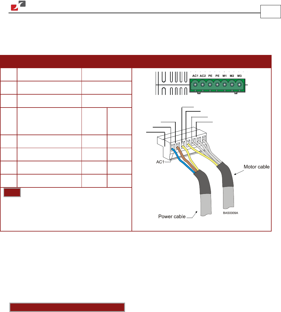
3.5.2. Connecting the Power Cables
The main power connector, which is located on the bottom of the Bassoon, includes the
following pins:
Pin Function Cable Pin Positions
AC1 Main Voltage Phase 1 Power
AC2 Main Voltage Phase 2 Power
PE Protective earth Power
AC
Motor
Cable
DC
Motor
Cable
PE Protective earth Motor Motor
M1 Motor phase Motor N/C
M2 Motor phase Motor Motor
M3 Motor phase Motor Motor
Note:
When connecting several motors, all
must be wired in an identical manner.
Table 2: Connector for Main Power and Motor Cables
3.5.2.1. Connecting the Motor Cable
Connect the motor power cable to the M1, M2, M3 and PE terminals of the main power
connector. The phase connection order is arbitrary because the Composer will establish the
proper commutation automatically during setup. However, if you plan to copy the set-up to
other drives, then the phase order on all copy drives must be the same.
Notes for connecting the motor cables:
• For best immunity, it is highly recommended to use a shielded (not twisted) cable for the
motor connection. A 4-wire shielded cable should be used. The gauge is determined by the
actual current consumption of the motor.
• Connect the shield of the cable to the closest ground connection at the motor end.
• The fourth wire should be used for the ground connection between the motor and the
second PE terminal of the Bassoon.
• Be sure that the motor chassis is properly grounded.
AC2
AC1
PE
PE
M1
M2
M3