
Manual


Table Of Contents
- Chapter 1: Safety Information
- Chapter 2: Introduction
- Chapter 3: Installation
- 3.1. Before You Begin
- 3.2. Unpacking the Drive Components
- 3.3. Assembling the Heatsink
- 3.4. Mounting the Bassoon
- 3.5. Connecting the Cables
- 3.5.1. Wiring the Bassoon
- 3.5.2. Connecting the Power Cables
- 3.5.3. Connecting the Auxiliary Power Cable (J4)
- 3.5.4. Feedback and Control Cable Assemblies
- 3.5.5. Main Feedback Cable (Port J3)
- 3.5.6. Main and Auxiliary Feedback Combinations
- 3.5.6.1. Main Encoder Buffered Outputs or Emulated Encoder Outputs Option on Feedback B (J2) (YA[4]=4)
- 3.5.6.2. Differential Auxiliary Encoder Input Option on Feedback B (J2) (YA[4]=2)
- 3.5.6.3. Single-Ended Auxiliary Input Option on Feedback B (J2) (YA[4]=2)
- 3.5.6.4. Pulse-and-Direction Input Option on FEEDBACK B (J2) (YA[4]=0)
- 3.5.7. I/O Cables
- 3.5.8. Communication Cable (Port J1, J8, J9)
- 3.6. Powering Up
- 3.7. Initializing the System
- Chapter 4: Technical Specifications
Bassoon Installation Guide Installation
MAN-BASIG (Ver. 1.502)
www.elmomc.com
22
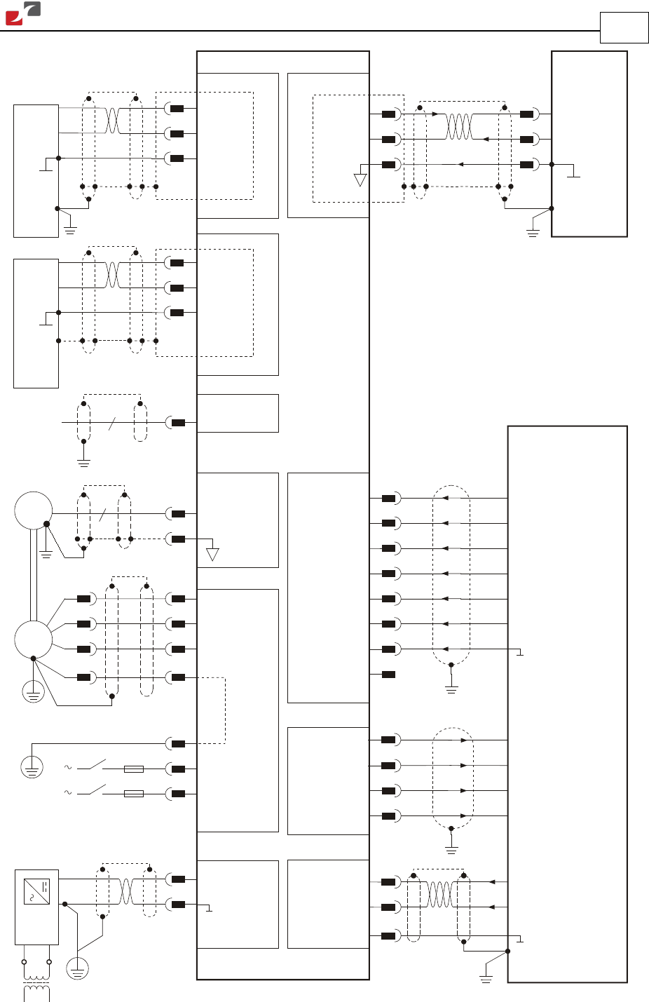
M
M3
M2
M1
PE
AC2
PE
J4
J2
J3
Power
Connector
PC RS232
Bassoon
ANALIN1 +
ANALIN1 -
ANLRET
ANALIN1 +
ANALIN1 -
ANLRET
J7
J5
J6
IN1
IN2
IN3
IN4
IN5
IN6
INRET
INRET
OUT1
OUTRET1
OUT2
OUTRET2
Tx
Rx
COMRET
AC1
Controller
AUX.
SUPPLY 24V
DC
RS-232 J1
Feedback B
Feedback A
Main Feedback
+24v
BAS0010A
Isolated
Transformer
Drain
Wire
/ Shield
4
Drain
Wire
/ Shield
Bassoon
CAN_H
CAN_L
CAN_GND
CAN_SHLD
Drain
wire
/ Shield
CANopen J8
CAN
Controller
CAN_H
CAN_L
CAN_GND
CAN_SHLD
Drain
wire
/ Shield
CANopen J9
Figure 6: Bassoon Detailed Connection Diagram