
Manual


Table Of Contents
- Chapter 1: Safety Information
- Chapter 2: Introduction
- Chapter 3: Installation
- 3.1. Before You Begin
- 3.2. Unpacking the Drive Components
- 3.3. Assembling the Heatsink
- 3.4. Mounting the Bassoon
- 3.5. Connecting the Cables
- 3.5.1. Wiring the Bassoon
- 3.5.2. Connecting the Power Cables
- 3.5.3. Connecting the Auxiliary Power Cable (J4)
- 3.5.4. Feedback and Control Cable Assemblies
- 3.5.5. Main Feedback Cable (Port J3)
- 3.5.6. Main and Auxiliary Feedback Combinations
- 3.5.6.1. Main Encoder Buffered Outputs or Emulated Encoder Outputs Option on Feedback B (J2) (YA[4]=4)
- 3.5.6.2. Differential Auxiliary Encoder Input Option on Feedback B (J2) (YA[4]=2)
- 3.5.6.3. Single-Ended Auxiliary Input Option on Feedback B (J2) (YA[4]=2)
- 3.5.6.4. Pulse-and-Direction Input Option on FEEDBACK B (J2) (YA[4]=0)
- 3.5.7. I/O Cables
- 3.5.8. Communication Cable (Port J1, J8, J9)
- 3.6. Powering Up
- 3.7. Initializing the System
- Chapter 4: Technical Specifications
Bassoon Installation Guide Installation
MAN-BASIG (Ver. 1.502)
www.elmomc.com
21
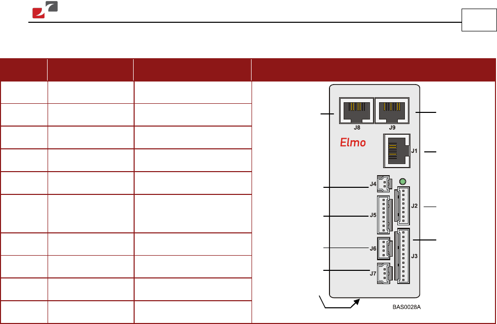
The following connectors are used for wiring the Bassoon.
Port Type Function Connector Location
J8 8-Pin RJ-45 CANopen
J9 8-Pin RJ-45 CANopen
J1 8-Pin RJ-45 RS-232
J2 8-Pin Molex Auxiliary Feedback
J3 12-Pin Molex Main Feedback
J4 2-Pin Molex Auxiliary power
supply
J5 8-Pin Molex Digital input
J6 4-Pin Molex Digital output
J7 3-Pin Molex Analog input
Power 7-Pin Phoenix Main power
Table 1: Bassoon Connectors
Auxiliary
Power
Supply
Digital Input
Digital Output
CANopen
Auxiliary
Feedback
Main
Feedback
Main
CANopen
RS232
Analog Input