
Manual


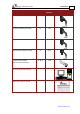


Table Of Contents
- Chapter 1: Safety Information
- Chapter 2: Introduction
- Chapter 3: Installation
- 3.1. Before You Begin
- 3.2. Unpacking the Drive Components
- 3.3. Assembling the Heatsink
- 3.4. Mounting the Bassoon
- 3.5. Connecting the Cables
- 3.5.1. Wiring the Bassoon
- 3.5.2. Connecting the Power Cables
- 3.5.3. Connecting the Auxiliary Power Cable (J4)
- 3.5.4. Feedback and Control Cable Assemblies
- 3.5.5. Main Feedback Cable (Port J3)
- 3.5.6. Main and Auxiliary Feedback Combinations
- 3.5.6.1. Main Encoder Buffered Outputs or Emulated Encoder Outputs Option on Feedback B (J2) (YA[4]=4)
- 3.5.6.2. Differential Auxiliary Encoder Input Option on Feedback B (J2) (YA[4]=2)
- 3.5.6.3. Single-Ended Auxiliary Input Option on Feedback B (J2) (YA[4]=2)
- 3.5.6.4. Pulse-and-Direction Input Option on FEEDBACK B (J2) (YA[4]=0)
- 3.5.7. I/O Cables
- 3.5.8. Communication Cable (Port J1, J8, J9)
- 3.6. Powering Up
- 3.7. Initializing the System
- Chapter 4: Technical Specifications

Bassoon Installation Guide Installation
MAN-BASIG (Ver. 1.502)
www.elmomc.com
19
Figure 4: Mounting the Bassoon on a DIN Rail
3.4.2. Mounting Directly onto a Wall
The mounting strips at the back of the Bassoon enable it to be screwed directly into a wall. If it
is not already assembled in the upper slot in the back of the Bassoon, assemble the upper
mounting tab now.
To mount the Bassoon onto a wall:
1. On the back of the drive, fully extend the top mounting strip so that the ends with the
holes are exposed. (The bottom strip is delivered already extended.)
2. Mount the Bassoon vertically onto the wall with two M4 round head screws and washers,
one through the top hole of the mounting strip and one at the bottom.
Figure 5: Extending the Mounting Strips and Attaching the Screws