Bassoon Digital Servo Drive Installation Guide July 2014 (Ver. 1.502) www.elmomc.
Notice This guide is delivered subject to the following conditions and restrictions: • This guide contains proprietary information belonging to Elmo Motion Control Ltd. Such information is supplied solely for the purpose of assisting users of the Bassoon servo drive in its installation. • The text and graphics included in this manual are for the purpose of illustration and reference only. The specifications on which they are based are subject to change without notice.
Revision History Version Date Ver. 1.0 Release Initial release Ver. 1.3 Apr 2008 Updated Power Ratings Table in Section 0 Ver. 1.4 Aug 2008 Added Section 3.5.6.4: Differential Pulse-and-Direction Input Ver. 1.5 Dec 2011 Formatted according to new template and new drawing with fan added Ver. 1.501 Feb 2013 Added a caution and recommendation on the type of cleaning solution to use for the Elmo unit. Ver. 1.
Elmo Worldwide Head Office Elmo Motion Control Ltd. 60 Amal St., POB 3078, Petach Tikva 49516 Israel Tel: +972 (3) 929-2300 • Fax: +972 (3) 929-2322 • info-il@elmomc.com North America Elmo Motion Control Inc. 42 Technology Way, Nashua, NH 03060 USA Tel: +1 (603) 821-9979 • Fax: +1 (603) 821-9943 • info-us@elmomc.com Europe Elmo Motion Control GmbH Hermann-Schwer-Strasse 3, 78048 VS-Villingen Germany Tel: +49 (0) 7721-944 7120 • Fax: +49 (0) 7721-944 7130 • info-de@elmomc.
Bassoon Installation Guide MAN-BASIG (Ver. 1.502) Table of Contents Chapter 1: 1.1. 1.2. 1.3. 1.4. 1.5. Warnings.....................................................................................................................9 Cautions ......................................................................................................................9 Directives and Standards ......................................................................................... 10 CE Marking Conformance .........
Bassoon Installation Guide Table of Contents MAN-BASIG (Ver. 1.502) 3.5.6.2. 3.6. 3.7. Differential Auxiliary Encoder Input Option on Feedback B (J2) (YA[4]=2) .................................................................................. 36 3.5.6.3. Single-Ended Auxiliary Input Option on Feedback B (J2) (YA[4]=2) ................................................................................................. 37 3.5.6.4. Pulse-and-Direction Input Option on FEEDBACK B (J2) (YA[4]=0)39 3.5.7.
Bassoon Installation Guide Table of Contents MAN-BASIG (Ver. 1.502) 4.8. I/Os .......................................................................................................................... 62 4.8.1. Digital Input Interfaces ............................................................................. 63 4.8.2. Digital Output Interface ............................................................................ 64 4.8.3. Analog Input (J7) ......................................................
Bassoon Installation Guide 8 MAN-BASIG (Ver. 1.502) Chapter 1: Safety I nform ation In order to achieve the optimum, safe operation of the Bassoon servo drive, it is imperative that you implement the safety procedures included in this installation guide. This information is provided to protect you and to keep your work area safe when operating the Bassoon and accompanying equipment. Please read this chapter carefully before you begin the installation process.
Bassoon Installation Guide Safety Information MAN-BASIG (Ver. 1.502) 1.1. Warnings • To avoid electric arcing and hazards to personnel and electrical contacts, never connect/disconnect the servo drive while the power source is on. • Power cables can carry a high voltage, even when the motor is not in motion. Disconnect the Bassoon from all voltage sources before it is opened for servicing. • The Bassoon servo drive contains grounding conduits for electric current protection.
Safety Information Bassoon Installation Guide MAN-BASIG (Ver. 1.502) 1.3.
Bassoon Installation Guide 11 MAN-BASIG (Ver. 1.502) Chapter 2: I ntroduction This installation guide describes the Bassoon servo drive and the steps for its wiring, installation and powering up. Following these guidelines ensures maximum functionality of the drive and the system to which it is connected. 2.1.
Introduction Bassoon Installation Guide MAN-BASIG (Ver. 1.502) 2.2.3. Position Control • Programmable PIP control filter • Programmable notch and low-pass filters • Position follower mode for monitoring the motion of the slave axis relative to a master axis, via an auxiliary encoder input • Pulse-and-direction inputs • Sample time: four times that of current loop • Fast event capturing inputs 2.2.4.
Introduction Bassoon Installation Guide MAN-BASIG (Ver. 1.502) • Resolver • • Programmable 10 to 15 bit resolution Up to 512 revolutions per second (RPS) Encoder outputs, buffered, differential Tachometer and Potentiometer Two inputs for Tachometer Feedback: • Up to ±50 VDC • Up to ±20 VDC Potentiometer Feedback: • 0 to 5 V voltage range • Resistance: 100 Ω to 1000 Ω Elmo drives provide supply voltage for all the feedback options. 2.2.7.
Bassoon Installation Guide Introduction MAN-BASIG (Ver. 1.502) 2.4. How to Use this Guide In order to install and operate your Elmo Bassoon servo drive, you will use this manual in conjunction with a set of Elmo documentation.
Bassoon Installation Guide 15 MAN-BASIG (Ver. 1.502) Chapter 3: I nstallation The Bassoon must be installed in a suitable environment and properly connected to its voltage supplies and the motor. 3.1. Before You Begin 3.1.1. Site Requirements You can guarantee the safe operation of the Bassoon by ensuring that it is installed in an appropriate environment.
Installation Bassoon Installation Guide MAN-BASIG (Ver. 1.502) Component Connector Described in Section Main Feedback Cable J3 3.5.5 Auxiliary Feedback (if needed) J2 3.5.6 Digital Input Cable (if needed) J5 3.5.6 Digital Output Cable (if needed) J6 3.5.6 J1, J8, J9 3.5.8 Communication Cables (RS-232 and/or CANopen) Drawing 1 PC for drive setup and tuning Motor data sheet or manual www.elmomc.
Installation Bassoon Installation Guide MAN-BASIG (Ver. 1.502) 3.1.3. AC Power Requirements Below are the Bassoon’s AC power requirements: Component Single-Phase Supply Voltage Circuit breaker current rating 200% to 300% of drive current Circuit breaker voltage rating 230 VAC Contactor Up to 200% of drive current 3.2.
Bassoon Installation Guide Installation MAN-BASIG (Ver. 1.502) 3.3. Assembling the Heatsink When an external heatsink device is required, attach it with four screws to the left side of the Bassoon, as depicted in the following diagrams. BAS0033A BAS0041A-DWG Figure 3: Attaching the Heatsink To mount the finned heatsink use M4 screws and spring washers. To mount the L-shaped heatsink use conical head M4 screws. 3.4.
Bassoon Installation Guide Installation MAN-BASIG (Ver. 1.502) Figure 4: Mounting the Bassoon on a DIN Rail 3.4.2. Mounting Directly onto a Wall The mounting strips at the back of the Bassoon enable it to be screwed directly into a wall. If it is not already assembled in the upper slot in the back of the Bassoon, assemble the upper mounting tab now. To mount the Bassoon onto a wall: 1. On the back of the drive, fully extend the top mounting strip so that the ends with the holes are exposed.
Bassoon Installation Guide Installation MAN-BASIG (Ver. 1.502) 3.5. Connecting the Cables The Bassoon has 10 connectors. 3.5.1. Wiring the Bassoon Once the Bassoon is mounted, you are ready to wire the device. Proper wiring, grounding and shielding are essential for ensuring safe, immune and optimal servo performance of the Bassoon. Caution: Follow these instructions to ensure safe and proper wiring: • Use twisted-pair shielded wires for control, feedback and communication ports.
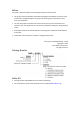
Installation Bassoon Installation Guide MAN-BASIG (Ver. 1.502) 21 The following connectors are used for wiring the Bassoon.
Installation Bassoon Installation Guide MAN-BASIG (Ver. 1.502) Bassoon PC RS232 RS-232 J1 CANopen J8 CAN_H CAN Controller Tx CAN_L Drain wire / Shield 22 Rx CAN_GND COMRET CAN_SHLD Drain Wire / Shield CAN_H Bassoon CAN_L Drain wire / Shield CAN_GND CAN_SHLD CANopen J9 Feedback B J2 Controller Feedback A Main Feedback J3 J5 IN1 IN2 4 Drain Wire / Shield IN3 IN4 M3 M Power Connector IN5 M2 IN6 M1 INRET PE INRET J6 PE OUT1 AC2 OUTRET1 AC1 OUT2 OUTRET2 AUX.
Installation Bassoon Installation Guide MAN-BASIG (Ver. 1.502) 3.5.2.
Bassoon Installation Guide Installation MAN-BASIG (Ver. 1.502) Figure 7: AC Motor Power Connection Diagram 3.5.2.2. Connecting the Main Power Cable Connect the main power supply cable to the AC1, AC2 and PE terminals of the main power connector. Notes for connecting the AC power cable: • For best immunity, a shielded (not twisted) cable is recommended (not mandatory) for the AC power supply cable. A 3-wire shielded cable should be used.
Installation Bassoon Installation Guide MAN-BASIG (Ver. 1.502) 3.5.3. Connecting the Auxiliary Power Cable (J4) Connect the auxiliary power supply to the J4 port on the front of the Bassoon, using a 2-pin Molex plug. Remember, you are working with DC power; be sure to exercise caution. The required voltage is 24 VDC. Notes for 24 VDC auxiliary power supply connections: • Use a 24 or 26 AWG twisted pair shielded cable.
Bassoon Installation Guide Installation MAN-BASIG (Ver. 1.502) 3.5.4. Feedback and Control Cable Assemblies The Auxiliary Power Cable (J4), the Feedback cables (J2 and J3) and the I/O cables (J5, J6 and J7) all use 2 mm pitch Molex “Sherlock” connectors. These connectors snap together quite easily, but require a small standard screwdriver for disassembly.
Installation Bassoon Installation Guide MAN-BASIG (Ver. 1.502) 3.5.5. Main Feedback Cable (Port J3) The main feedback cable is used to transfer feedback data from the motor to the drive.
Installation Bassoon Installation Guide 28 MAN-BASIG (Ver. 1.502) The wiring of the Main Feedback cable depends on the type of device used. Incremental Encoder wiring, Interpolated Analog Encoder wiring and Resolver wiring are shown in the table below.
Installation Bassoon Installation Guide MAN-BASIG (Ver. 1.
Installation Bassoon Installation Guide MAN-BASIG (Ver. 1.502) Figure 13: Main Feedback – Interpolated Analog (Sine/Cosine) Encoder Connection Diagram Figure 14: Main Feedback – Resolver Connection Diagram www.elmomc.
Installation Bassoon Installation Guide MAN-BASIG (Ver. 1.
Bassoon Installation Guide Installation MAN-BASIG (Ver. 1.502) Figure 17: Main Feedback – Potentiometer Feedback with Digital Hall Sensor Connection Diagram for Brushless Motors Potentiometer Bassoon Feedback A POT +5V SUPRET 8 6 +5v Supply 4 Voltage Return 5 BAS0044A Figure 18: Main Feedback – Potentiometer Feedback Connection Diagram for Brush Motors and Voice Coils www.elmomc.
Bassoon Installation Guide Installation MAN-BASIG (Ver. 1.502) Figure 19: Main Feedback – Stegmann Feedback Connection Diagram Figure 20: Main Feedback – Heidenhain Feedback Connection Diagram www.elmomc.
Installation Bassoon Installation Guide MAN-BASIG (Ver. 1.502) 3.5.6. 34 Main and Auxiliary Feedback Combinations The Main Feedback is always used in motion control devices whereas the Auxiliary Feedback is often, but not always used. The Auxiliary Feedback port, FEEDBACK B (J2), can be used in combination with the Main Feedback port, FEEDBACK A (J3).
Installation Bassoon Installation Guide MAN-BASIG (Ver. 1.502) 3.5.6.1. Main Encoder Buffered Outputs or Emulated Encoder Outputs Option on Feedback B (J2) (YA[4]=4) Through FEEDBACK B the Bassoon can provide buffered main, or emulated, encoder signals to another controller or drive. This option can be used when: • The Bassoon is used as a current amplifier to provide position data to the position controller. • The Bassoon is used in velocity mode, to provide position data to the position controller.
Installation Bassoon Installation Guide MAN-BASIG (Ver. 1.502) Controller Feedback B - J2 SUPRET +5v INDEXO- Bassoon INDEXO CHBOCHBO CHAOCHAO 1 2 3 4 5 6 7 8 INDEXINDEX CHBCHB CHACHA BAS0023A Figure 21: Main Encoder Buffered Output or Emulated Encoder Output on J2 - Connection Diagram 3.5.6.2. Differential Auxiliary Encoder Input Option on Feedback B (J2) (YA[4]=2) The Bassoon can be used as a slave by receiving the position (on Port B) of the master encoder data in Follower or ECAM mode.
Installation Bassoon Installation Guide MAN-BASIG (Ver. 1.502) Encoder Feedback B - J2 SUPRET +5v Encoder supply voltage return 2 2 Encoder +5v Supply 3 INDEXBassoon 1 4 INDEX 5 CHB- 6 CHB 7 CHA- 8 CHA INDEXINDEX CHBCHB CHACHA BAS0024A Figure 22: Differential Auxiliary Encoder Inputs on J2 - Connection Diagram 3.5.6.3.
Installation Bassoon Installation Guide MAN-BASIG (Ver. 1.502) Encoder Feedback B - J2 SUPRET +5v 1 1 2 2 2 Supply Voltage Return +5v Bassoon 3 INDEX 4 4 INDEX 5 CHB 6 6 CHB 7 CHA 8 8 CHA BAS0025A Figure 23: Single-Ended Auxiliary Encoder inputs on J2 - Connection Diagram www.elmomc.
Installation Bassoon Installation Guide MAN-BASIG (Ver. 1.502) 3.5.6.4. Pulse-and-Direction Input Option on FEEDBACK B (J2) (YA[4]=0) This mode is used for input of differential or single-ended pulse-and-direction position commands.
Bassoon Installation Guide Installation MAN-BASIG (Ver. 1.
Installation Bassoon Installation Guide MAN-BASIG (Ver. 1.502) 3.5.7. I/O Cables The following table lists the I/O cables that you should connect according to your specific requirements: I/O Description Total Port Digital input 6 J5 Digital output 2 J6 Analog input 1 J7 3.5.7.1. Digital Input (Port J5) Notes for connecting the digital input cable: • Use 24 or 26 AWG twisted pair shielded cable.
Bassoon Installation Guide Installation MAN-BASIG (Ver. 1.502) Figure 26: Digital Input Connection Diagram www.elmomc.
Installation Bassoon Installation Guide MAN-BASIG (Ver. 1.502) 3.5.7.2. Digital Output (Port J6) Notes for connecting the digital output cable: • Use 24 or 26 AWG twisted pair shielded cable. • Connect the cable shield to the ground near the controller according to the manufacturer’s recommendations.
Installation Bassoon Installation Guide MAN-BASIG (Ver. 1.502) 3.5.7.3. 44 Analog Input (Port J7) Notes for connecting the analog input cable: • Use 24, 26 or 28 AWG twisted pair shielded cable. • Connect the cable shield to the ground near the signal source (controller) according to the manufacturer’s recommendations.
Installation Bassoon Installation Guide MAN-BASIG (Ver. 1.502) 3.5.8. Communication Cable (Port J1, J8, J9) The communication cables use an 8-pin RJ-45 plug that connects to the J1 port (RS-232), the J8 port (CANopen) and/or J9 (CANopen) on the front of the Bassoon. The communication interface may differ according to the user’s hardware. The Bassoon can communicate using the following options: a. RS-232, full duplex b. CANopen c.
Installation Bassoon Installation Guide MAN-BASIG (Ver. 1.502) Figure 29: RS-232 Connection Diagram 3.5.8.2. CANopen Communication Notes for connecting the CANopen communication cable (J8 and/or J9 port): • Use a 26 or 28 AWG twisted pair shielded cable. The cable should have an aluminum foil shield covered by copper braid with a drain wire. • Connect the shield to the ground of the host (PC). Usually, this connection is soldered internally inside the connector at the PC end.
Bassoon Installation Guide Installation MAN-BASIG (Ver. 1.502) 47 Caution: When installing CANopen communication, ensure that each servo drive is allocated a unique ID. Otherwise, the CANopen network may hang. Figure 30: CANopen Connection Diagram www.elmomc.
Bassoon Installation Guide Installation MAN-BASIG (Ver. 1.502) 3.6. Powering Up After the Bassoon has been mounted, check that the cables are intact. The Bassoon servo drive is then ready to be powered up. Caution: Before applying power, ensure that the AC supply is within the range specified for your specific type of Bassoon. To power up the system, first switch on the auxiliary power and then the main power supply.
Bassoon Installation Guide 49 MAN-BASIG (Ver. 1.502) Chapter 4: Technical Specifications This chapter provides detailed technical information regarding the Bassoon. This includes its dimensions, power ratings, the environmental conditions under which it can be used, the standards to which it complies and other specifications. 4.1. Features The Bassoon's features determine how it controls motion, as well as how it processes host commands, feedback and other input. 4.1.1.
Bassoon Installation Guide Technical Specifications MAN-BASIG (Ver. 1.502) 4.1.5.
Bassoon Installation Guide Technical Specifications MAN-BASIG (Ver. 1.502) 4.1.7. Built-In Protection • Software error handling • Abort (hard stops and soft stops) • Status reporting • Protection against Shorts between motor power outputs Shorts between motor power outputs and power input/return Failure of internal power supplies Overheating Over/Under voltage Loss of feedback Following error Current limits www.elmomc.
Technical Specifications Bassoon Installation Guide MAN-BASIG (Ver. 1.502) 4.2. Bassoon Dimensions 4.2.1. Bassoon without a Fan 44(1.7) 4(0.16) J8 J9 J4 J2 120(4.7) 129(5.1) 105(4.1) J1 J5 J6 J3 J7 4(0.16) 76mm(3in) AC1 AC2 PE PE M1 M2 M3 BAS0003A www.elmomc.
Technical Specifications Bassoon Installation Guide MAN-BASIG (Ver. 1.502) 4.2.2. Bassoon with a Fan General Specifications Feature Units 1/230 3/230 Minimum supply voltage VAC 30 Nominal supply voltage VAC 230 Maximum supply voltage VAC 270 320 1050 Maximum continuous power output W Efficiency at rated power (at nominal conditions) % >97 Auxiliary supply voltage VDC 24 ± 20% Auxiliary power supply VA 8 Amplitude sinusoidal/DC continuous A 1 3. 3 6/230 1900 6 www.elmomc.
Technical Specifications Bassoon Installation Guide MAN-BASIG (Ver. 1.502) Feature Units 1/230 3/230 54 6/230 current Sinusoidal continuous RMS current limit (Ic) A Peak current limit A 0.7 Weight Dimensions No #2 (fins) #4 (fins and fan) 400 W g (oz) 350 g (12.35) 490 g (17.28) mm (in) 105 x 44 x 76 105 x 56 x 76 (4.13" x 1.73" x 3") 505 g (17.81) 105 x 66.5 x 76 (4.13" x 2.20" x 3") (4.13" x 2.60" x 3") Digital in/Digital out/Analog in 6/2/1 Mounting method 4.3. 4.
Technical Specifications Bassoon Installation Guide MAN-BASIG (Ver. 1.502) 4.4. 55 Bassoon Connectors The following connectors are used for wiring the Bassoon. 4.4.1. Connector Types The table below shows the connector panel of the Bassoon. Pins Type Connector Maker & No.
Technical Specifications Bassoon Installation Guide MAN-BASIG (Ver. 1.502) 4.4.2.
Technical Specifications Bassoon Installation Guide MAN-BASIG (Ver. 1.502) 4.5. 57 Auxiliary Power Supply (J4) Feature Details Auxiliary power supply DC source only Auxiliary supply input voltage 24 V ±20% Auxiliary supply input power 8 VA (maximum) Connector Location Auxiliary Power supply 4.6. Control Specifications 4.6.1.
Technical Specifications Bassoon Installation Guide MAN-BASIG (Ver. 1.502) 4.6.2.
Technical Specifications Bassoon Installation Guide MAN-BASIG (Ver. 1.502) 4.7. Feedback The Bassoon can receive and process feedback input from diverse types of devices. 4.7.1. Feedback Supply Voltage Feature Details J3 (main encoder) supply voltage 5 V ±5% @ 200 mA maximum J2 (auxiliary encoder) supply voltage 5 V ±5% @ 200 mA maximum 4.7.2.
Technical Specifications Bassoon Installation Guide MAN-BASIG (Ver. 1.502) 4.7.3. Digital Halls Feature Details Halls inputs • HA, HB, HC. • Single ended inputs • Built in hysteresis for noise immunity. Input voltage Nominal operating range: 0 V < VIn_Hall < 5 V Maximum absolute: -1 V < VIn_Hall < 15 V High level input voltage: V InHigh > 2.5 V Low level input voltage: V InLow < 1 V Input current Sink current (when input pulled to the common): 3 mA Source current: 1.
Technical Specifications Bassoon Installation Guide MAN-BASIG (Ver. 1.502) 4.7.5. Resolver Feature Details Resolver format • Sine/Cosine • Differential Input resistance Differential 2.49 kΩ Resolution Programmable: 10 to 15 bits Maximum electrical frequency (RPS) 512 revolutions/sec Resolver transfer ratio 0.5 Reference frequency 1/Ts (Ts = sample time in seconds) Reference voltage Supplied by the Bassoon Reference current up to ±50 mA 4.7.6.
Technical Specifications Bassoon Installation Guide MAN-BASIG (Ver. 1.502) 4.7.7. Potentiometer Feature Details Potentiometer Format Single-ended Operating Voltage Range 0 to 5 V supplied by the Bassoon Potentiometer Resistance 100 Ω to 1 kΩ … above this range, linearity is affected detrimentally Input Resistance 100 kΩ Resolution 14 Bit 4.7.8.
Technical Specifications Bassoon Installation Guide MAN-BASIG (Ver. 1.502) 4.8.1. Digital Input Interfaces Feature Type of input Details Connector Location • Optically isolated • Single ended • PLC level Input current Iin = Vin − 6.5V 2500Ω * Iin = 2.2 mA @ Vin = 12 V Input current for high speed inputs Iin = Vin − 6.5V 1250Ω Digital Input * Iin = 4.4 mA @ Vin = 12 V High-level input voltage 12 V < Vin < 30 V, 24 V typical Low-level input voltage 0 V < Vin < 6.
Technical Specifications Bassoon Installation Guide MAN-BASIG (Ver. 1.502) 4.8.2. Digital Output Interface Feature Type of output Details Connector Location • Optically isolated • Open collector and open emitter Maximum supply output (Vcc) 30 V Maximum output current Io (max) (Vout = Low) Iout (max) ≤ 10 mA VOL @ maximum output voltage (low level) Vout (on) ≤ 0.3 V + 0.02 * Iout (10 mA) RL External resistor RL must be selected to limit output current to no more than 10 mA.
Technical Specifications Bassoon Installation Guide MAN-BASIG (Ver. 1.502) 4.8.3. 65 Analog Input (J7) Feature Details Maximum operating differential mode voltage ±10 V Maximum absolute differential input voltage ±16 V Differential input resistance 3 kΩ Analog input command resolution Connector Location 14-bit inputs Analog Input 4.9. Communications Specification Details RS-232 Connector Location Signals: • RxD , TxD , Gnd • Full duplex, serial communication for setup and control.
Technical Specifications Bassoon Installation Guide MAN-BASIG (Ver. 1.502) 4.10. Pulse-Width Modulation (PWM) Feature Details PWM resolution 12-bit PWM switching frequency on the load 2/ Ts (factory default 22 kHz on the motor) 4.11.
Bassoon Installation Guide Technical Specifications MAN-BASIG (Ver. 1.502) BAS_L_Shape Figure 35: L-Shaped Heat Sink Dimensions www.elmomc.
Technical Specifications Bassoon Installation Guide MAN-BASIG (Ver. 1.502) 4.12. Compliance with Standards Specification Details Quality Assurance ISO 9001:2008 Quality Management Design Approved IEC/EN 61800-5-1, Safety Printed wiring for electronic equipment (clearance, creepage, spacing, conductors sizing, etc.) MIL-HDBK- 217F Reliability prediction of electronic equipment (rating, de-rating, stress, etc.
Technical Specifications Bassoon Installation Guide MAN-BASIG (Ver. 1.