` Cornet Digital Servo Drive Installation Guide July 2014 (Ver. 1.502) www.elmomc.
Notice This guide is delivered subject to the following conditions and restrictions: a. This guide contains proprietary information belonging to Elmo Motion Control Ltd. Such information is supplied solely for the purpose of assisting users of the Cornet servo drive in its installation. b. The text and graphics included in this manual are for the purpose of illustration and reference only. The specifications on which they are based are subject to change without notice. c.
Elmo Worldwide Head Office Elmo Motion Control Ltd. 64 Gisin St., P.O. Box 463, Petach Tikva 49103 Israel Tel: +972 (3) 929-2300 • Fax: +972 (3) 929-2322 • info-il@elmomc.com North America Elmo Motion Control Inc. 42 Technology Way, Nashua, NH 03060 USA Tel: +1 (603) 821-9979 • Fax: +1 (603) 821-9943 • info-us@elmomc.com Europe Elmo Motion Control GmbH Steinkirchring 1, D-78056, Villingen-Schwenningen Germany Tel: +49 (0) 7720-85 77 60 • Fax: +49 (0) 7720-85 77 70 • info-de@elmomc.
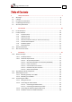
Cornet Installation Guide MAN-CORIG (Ver. 1.502) Table of Contents 1. Safety Information .......................................................................................... 7 1.1. 1.2. 1.3. 1.4. 1.5. 2. Introduction ................................................................................................. 10 1.6. 1.7. 1.8. 1.9. 3. Warnings.....................................................................................................................8 Cautions .......................
Cornet Installation Guide Table of Contents MAN-CORIG (Ver. 1.502) 1.13.5. Main Feedback Cable (FEEDBACK A) ........................................................ 28 1.13.6. Main and Auxiliary Feedback Combinations ............................................ 35 1.13.7. Auxiliary Feedback (FEEDBACK B)............................................................. 36 1.13.7.1. Main Encoder Buffered Outputs or Emulated Encoder Outputs Option on FEEDBACK B (YA[4]=4) .........................................
Cornet Installation Guide Table of Contents MAN-CORIG (Ver. 1.502) 1.24. 1.25. 1.26. 1.27. 1.28. 1.23.1. Digital Input Interfaces (on the COMMITTED I/O port) ............................ 67 1.23.2. Digital Output Interface (on the General I/O Port) .................................. 68 1.23.3. Analog Input ............................................................................................. 69 Communications ........................................................................................
Cornet Installation Guide 7 MAN-CORIG (Ver. 1.502) 1. Safety I nform ation In order to achieve the optimum, safe operation of the Cornet servo drive, it is imperative that you implement the safety procedures included in this installation guide. This information is provided to protect you and to keep your work area safe when operating the Cornet and accompanying equipment. Please read this chapter carefully before you begin the installation process.
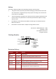
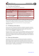
Cornet Installation Guide Safety Information MAN-CORIG (Ver. 1.502) 1.1. Warnings e. To avoid electric arcing and hazards to personnel and electrical contacts, never connect/disconnect the servo drive while the power source is on. f. Power cables can carry a high voltage, even when the motor is not in motion. Disconnect the Cornet from all voltage sources before it is opened for servicing. g. The Cornet servo drive contains grounding conduits for electric current protection.
Safety Information Cornet Installation Guide MAN-CORIG (Ver. 1.502) 1.3.
Cornet Installation Guide 10 MAN-CORIG (Ver. 1.502) 2. I ntroduction This installation guide describes the Cornet servo drive and the steps for its wiring, installation and powering up. Following these guidelines ensures maximum functionality of the drive and the system to which it is connected. 1.6.
Cornet Installation Guide Introduction MAN-CORIG (Ver. 1.502) 1.7.2. Velocity Control s. Fully digital t. Programmable PI and FFW (feed forward) control filters u. Sample rate two times current loop sample time v. “On-the-fly” gain scheduling w. Automatic, manual and advanced manual tuning and determination of optimal gain and phase margins 1.7.3. Position Control x. Programmable PIP control filter y. Programmable notch and low-pass filters z.
Cornet Installation Guide Introduction MAN-CORIG (Ver. 1.502) 1.7.6. Feedback Options jj. Incremental Encoder – up to 20 Mega-Counts (5 Mega-Pulse) per second kk. Digital Halls – up to 2 kHz ll. Incremental Encoder with Digital Halls for commutation – up to 20 Mega-Counts per second for encoder mm. Absolute Encoder nn.
Introduction Cornet Installation Guide MAN-CORIG (Ver. 1.502) 1.8. System Architecture Communication RS 232 and CANopen Analog Encoder or Resolver or Incremental Encoder Auxiliary Power Supply Controller I/Os 24 VDC Auxiliary Encoder Protection PWM Current Feedback Incremental Encoder Buffered Output or Emulated Output Power Stage Figure 1: Cornet System Block Diagram 1.9.
Introduction Cornet Installation Guide MAN-CORIG (Ver. 1.502) Programming CANopen Implementation Guide SimplIQ Software Manual SimplIQ Command Reference Manual Composer User Manual Setup Installation Cornet Installation Guide Figure 2: Elmo Documentation Hierarchy As depicted in the previous figure, this installation guide is an integral part of the Cornet documentation set, comprising: xx.
Cornet Installation Guide 15 MAN-CORIG (Ver. 1.502) 3. I nstallation The Cornet must be installed in a suitable environment and properly connected to its voltage supplies and the motor. 1.10. Before You Begin 1.10.1. Site Requirements You can guarantee the safe operation of the Cornet by ensuring that it is installed in an appropriate environment.
Installation Cornet Installation Guide MAN-CORIG (Ver. 1.502) 1.10.2.2. Recommended Wire Cross-Sections (All Models) Feature Connection Details AC input AC1, AC2, AC3 2.0 mm2 14 AWG Motor M1, M2, M3 2.0 mm2 14 AWG Protective earth PE, PE 2.0 mm2 14 AWG Auxiliary power +, – 0.5 to 1 mm2 18 to 24 AWG 1.10.2.3. Power Connectors Component Connector Main Power Cable Motor Cable Auxiliary Power Cable 1.10.2.4. Described in Section PE, AC1, AC2, and AC3 on Power Connector 1.13.2.
Installation Cornet Installation Guide MAN-CORIG (Ver. 1.502) 1.10.2.5. Feedback and I/O Connectors Component Port on Cornet Described in Section Main Feedback Cable FEEDBACK A 1.13.5 Auxiliary Feedback Cable (if needed) FEEDBACK B 1.13.7 Drawing COR016A Analog Inputs (if needed) ANALOG INPUTS 1.13.8.1 CEL0040A-DWG COR016A Digital Inputs Cable (if needed) Digital Outputs Cable (if needed) COMMITTED I/O 1.13.8.2 GENERAL I/O 1.13.8.3 www.elmomc.
Installation Cornet Installation Guide MAN-CORIG (Ver. 1.502) 1.10.2.6. Other Items Needed Component Diagram PC for drive setup and tuning Motor data sheet or manual 1.11. Unpacking the Drive Components Before you begin working with the Cornet system, verify that you have all of its components, as follows: aaa. The Cornet servo drive bbb. The Composer software and software manual The Cornet is shipped in a cardboard box with Styrofoam protection.
Cornet Installation Guide Installation MAN-CORIG (Ver. 1.502) 1.12. Mounting the Cornet The Cornet has been designed for two standard mounting options: ccc. Attaching directly to a wall with screws ddd. Mounting on a DIN rail With either type of mounting, be sure to leave about 10 cm (4 in) above and below the instrument for heat dissipation. 1.12.1. Mounting Directly onto a Wall The vertical mounting strip at the back of the Cornet enables you to screw the drive directly into a wall.
Cornet Installation Guide Installation MAN-CORIG (Ver. 1.502) 1.12.2. Mounting on a DIN Rail At the top rear of the Cornet, a horizontal groove lets you quickly and easily snap the drive onto a DIN rail in your work area. To mount the Cornet on a DIN rail: 2. Be sure that the vertical mounting strip (with the hole at the top) is pressed down fully and does not protrude from the top of the instrument. Figure 4: Mounting Strip Pressed Down Tilt the Cornet back towards the top part of the DIN rail.
Cornet Installation Guide Installation MAN-CORIG (Ver. 1.502) Press the Cornet down to a vertical position until it clicks onto the DIN rail. Figure 6: Cornet Mounted on a DIN Rail 1.13. Connecting the Cables The Cornet has 10 connectors. 1.13.1. Wiring the Cornet Once the Cornet is mounted, you are ready to wire the device. Proper wiring, grounding and shielding are essential for ensuring safe, immune and optimal servo performance of the Cornet.
Installation Cornet Installation Guide 22 MAN-CORIG (Ver. 1.502) jjj. Ensure that in normal operating conditions, the shielded wires and drain carry no current. The only time these conductors carry current is under abnormal conditions, when electrical equipment has become a potential shock or fire hazard while conducting external EMI interferences directly to ground, in order to prevent them from affecting the drive. Failing to meet this requirement can result in drive/controller/host failure. kkk.
Cornet Installation Guide Installation MAN-CORIG (Ver. 1.502) Figure 7: Cornet Detailed Connection Diagram www.elmomc.
Installation Cornet Installation Guide MAN-CORIG (Ver. 1.502) 1.13.2.
Cornet Installation Guide Installation MAN-CORIG (Ver. 1.502) 1.13.2.1. Connecting the Motor Cable Connect the motor power cable to the M1, M2, M3 and PE terminals of the main power connector. The phase connection order is arbitrary because the Composer will establish the proper commutation automatically during setup. However, if you plan to copy the set-up to other drives, then the phase order on all copy drives must be the same.
Installation Cornet Installation Guide MAN-CORIG (Ver. 1.502) 1.13.2.2. Connecting the Main Power Cable Connect the main power supply cable to the AC1, AC2 and AC3 terminals of the main power connector. Connect the Protective Earth wire to the nearest PE terminal on the terminal block. Notes for connecting the AC power cable: For best noise immunity, a shielded (not twisted) cable is recommended (not mandatory) for the AC power supply cable. A 4-wire shielded cable should be used.
Installation Cornet Installation Guide MAN-CORIG (Ver. 1.502) 1.13.3. Connecting the Auxiliary Supply Cable (24 V) Connect the auxiliary supply to the 24 VDC terminal block on the bottom of the Cornet. Remember, you are working with DC power; so be sure to exercise caution. Notes for 24 VDC auxiliary supply connections: Use a 24 AWG twisted pair shielded cable. For best results the shield should have aluminum foil covered by copper braid.
Cornet Installation Guide Installation MAN-CORIG (Ver. 1.502) 1.13.4. Feedback and Control Cable Assemblies The Cornet features easy-to-use D-Sub type connections for all Control and Feedback cables. Instructions and diagrams describing how to assemble those cables are presented below. 1. Use 24, 26 or 28 AWG twisted-pair shielded cables (24 AWG cable is recommended). For best results, the shield should have aluminum foil covered by copper braid. Use only a D-Sub connector with a metal housing.
Installation Cornet Installation Guide 29 MAN-CORIG (Ver. 1.
Installation Cornet Installation Guide MAN-CORIG (Ver. 1.
Installation Cornet Installation Guide MAN-CORIG (Ver. 1.502) Cornet Feedback A HC HB HA CHA CHACHB CHBINDEX INDEX+5V +5V SUPRET 1 10 2 6 5 15 14 8 7 Incremental Encoder with Hall Sensor Hall C Hall B Hall A CHA CHACHB CHBINDEX INDEX- 12 4 3 Encoder / Hall +5v Supply Hall / Encoder Supply / Voltage Return 9 11 13 COR0004A Figure 14: Main Feedback- Incremental Encoder Connection Diagram www.elmomc.
Installation Cornet Installation Guide MAN-CORIG (Ver. 1.502) Cornet Feedback A B- A+ 5 AB+ Sine / Cosine Encoder 6 A+ A- 15 B+ 14 B- 8 R+ R+ 7 R- R- 4 +5v Encoder +5v Supply 3 SUPRET 32 Encoder Supply Return COR0005A Figure 15: Main Feedback – Interpolated Analog (Sine/Cosine) Encoder Connection Diagram Cornet Feedback A Resolver S1 S3 S2 S4 R1 R2 6 5 15 14 8 7 S1 S3 S2 S4 R1 R2 COR0006A Figure 16: Main Feedback – Resolver Connection Diagram www.elmomc.
Cornet Installation Guide Installation MAN-CORIG (Ver. 1.502) Figure 17: Main Feedback – Stegmann Connection Diagram www.elmomc.
Cornet Installation Guide Installation MAN-CORIG (Ver. 1.502) Figure 18: Main Feedback – Heidenhain Connection Diagram www.elmomc.
Installation Cornet Installation Guide 35 MAN-CORIG (Ver. 1.502) 1.13.6. Main and Auxiliary Feedback Combinations The Main Feedback is always used in motion control devices whereas Auxiliary Feedback is often, but not always used. The Auxiliary Feedback connector on the Cornet, FEEDBACK B, has two ports, Port B1 and Port B2.
Installation Cornet Installation Guide 36 MAN-CORIG (Ver. 1.502) 1.13.7. Auxiliary Feedback (FEEDBACK B) When using one of the auxiliary feedback options, the relevant functionality of FEEDBACK B ports are software selected for that option. Refer to the Cornet Command Reference Manual for detailed information about FEEDBACK B setup. 1.13.7.1.
Cornet Installation Guide Installation MAN-CORIG (Ver. 1.502) FEEDBACK B, on the front of the Cornet, has a 15-pin D-Sub plug. Connect the Auxiliary Feedback cable, from the controller or other device, to FEEDBACK B using a 15-pin D-Sub socket with a metal housing. When assembling the Auxiliary Feedback cable, follow the instructions in Section 1.13.4 (Feedback and Control Cable Assemblies). Figure 19: Main Encoder Buffered Output or Emulated Encoder Output on FEEDBACK B Connection Diagram 1.13.7.2.
Installation Cornet Installation Guide 38 MAN-CORIG (Ver. 1.
Cornet Installation Guide Installation MAN-CORIG (Ver. 1.502) Figure 20: Differential Auxiliary Encoder Input Option on FEEDBACK B Connection Diagram www.elmomc.
Installation Cornet Installation Guide 40 MAN-CORIG (Ver. 1.502) 1.13.7.3. Single-Ended Auxiliary Input Option on FEEDBACK B (YA[4]=2) The Cornet can be used as a slave by receiving the position data (on Port B1) of the master encoder in Follower or ECAM mode. In this mode Port B2 provides differential buffered auxiliary outputs for the next slave axis in Follower or ECAM mode.
Cornet Installation Guide Installation MAN-CORIG (Ver. 1.502) Figure 21: Single-Ended Auxiliary Input Option on FEEDBACK B - Connection Diagram www.elmomc.
Installation Cornet Installation Guide 42 MAN-CORIG (Ver. 1.502) 1.13.7.4. Pulse-and-Direction Input Option on FEEDBACK B (YA[4]=0) This mode is used for input of differential or single-ended pulse-and-direction position commands on Port B1. In this mode Port B2 provides differential buffered pulse-and-direction outputs for another axis. Below are the signals on the Auxiliary Feedback ports when set up to run as a single-ended pulse-and-direction input: Port Pin Signal Function - 1 N.C.
Cornet Installation Guide Installation MAN-CORIG (Ver. 1.502) Figure 22: Pulse-and-Direction Input Option on FEEDBACK B - Connection Diagram www.elmomc.
Installation Cornet Installation Guide 44 MAN-CORIG (Ver. 1.502) Below are the signals on the Auxiliary Feedback ports when set up to run as a differential pulseand-direction input: Port Pin Signal Function - 1 N.C.
Installation Cornet Installation Guide 45 MAN-CORIG (Ver. 1.502) Figure 23: Pulse-and-Direction Input Option on FEEDBACK B - Connection Diagram 1.13.8. I/O Cables The Cornet has three I/O ports (ANALOG INPUTS, DIGITAL INPUTS AND DIGITAL OUTPUTS), which can be used to connect 2 analog inputs, 10 digital inputs and 6 separate digital outputs: LABEL ANALOG INPUTS COMMITTED I/O GENERAL I/O Total I/O Analog Input 2 - - 2 Digital Input - 10 - 10 Digital Output - - 6 6 www.elmomc.
Installation Cornet Installation Guide MAN-CORIG (Ver. 1.502) 1.13.8.1. Analog Inputs The Cornet servo drive is equipped with two differential, freely-programmable analog inputs. The ANALOG INPUTS port has a 9-pin D-Sub socket. When assembling an I/O cable for analog input, follow the instructions in Section 1.13.4 (Feedback and Control Cable Assemblies) using a 9-pin D-Sub plug with a metal case. Note: Analog Inputs 1 and 2 are functionally identical.
Cornet Installation Guide Installation MAN-CORIG (Ver. 1.502) 1.13.8.2. Digital Inputs (on the COMMITTED I/O Port) The Cornet servo drive is equipped has a 15-pin, high-density, D-Sub plug for digital inputs. When assembling an I/O cable for digital input follow the instructions in Section 1.13.4 (Feedback and Control Cable Assemblies) using a 15-pin, high-density, D-Sub socket with a metal case. The pins are described below.
Cornet Installation Guide Installation MAN-CORIG (Ver. 1.502) Figure 25: Digital Inputs (on the Committed I/O port) Connection Diagram www.elmomc.
Cornet Installation Guide Installation MAN-CORIG (Ver. 1.502) 1.13.8.3. Digital Outputs (on the GENERAL I/O Port) The Cornet servo drive has a 15-pin, high-density, D-Sub socket for digital outputs. When assembling an I/O cable for digital outputs, follow the instructions in Section 1.13.4 (Feedback and Control Cable Assemblies) using a 15-pin D-Sub plug with a metal case. The pins are described below.
Cornet Installation Guide Installation MAN-CORIG (Ver. 1.502) Figure 26: Digital Outputs (on the General I/O port) Connection Diagram www.elmomc.
Installation Cornet Installation Guide MAN-CORIG (Ver. 1.502) 1.13.9. Communication Cables The communication cables use an 8-pin RJ-45 plug that connect to the RS-232 and CAN ports on the front of the Cornet. The communication interface may differ according to the user’s hardware. The Cornet can communicate using the following options: RS-232, full duplex CAN RS-232 communication requires a standard, commercial 3-core null-modem cable connected from the Cornet to a serial interface on the PC.
Installation Cornet Installation Guide MAN-CORIG (Ver. 1.502) RS232 Communication PC RS232 Cornet Tx Rx COMRET 3 6 5 Drain Wire Shield of RJ connector COR0014A Figure 27: RS-232 Connection Diagram 1.13.9.2. CAN Communication (on the COMM.2 Ports) Notes for connecting the CAN communication cable: Use 26 or 28 AWG twisted pair shielded cables. For best results, the shield should have aluminum foil and covered by copper braid with a drain wire Connect the shield to the ground of the host (PC).
Installation Cornet Installation Guide MAN-CORIG (Ver. 1.
Cornet Installation Guide Installation MAN-CORIG (Ver. 1.502) 1.14. Powering Up After the Cornet has been mounted, check that the cables are intact. The Cornet servo drive is then ready to be powered up. Caution: Before applying power, ensure that the AC supply is within the range specified for your specific type of Cornet. 1.15. Initializing the System After the Cornet has been connected and mounted, the system must be set up and initialized.
Cornet Installation Guide 55 MAN-CORIG (Ver. 1.502) 2. Technical Specifications This chapter provides detailed technical information regarding the Cornet. This includes its dimensions, power ratings, the environmental conditions under which it can be used, the standards to which it complies and other specifications. 1.16. Features The Cornet's features determine how it controls motion, as well as how it processes host commands, feedback and other input. 1.16.1. vvv.
Cornet Installation Guide Technical Specifications MAN-CORIG (Ver. 1.502) llll. Absolute Encoder mmmm. Interpolated Analog (Sine/Cosine) Encoder – up to 250 kHz (analog signal) Internal Interpolation - up to x4096 Automatic Correction of amplitude mismatch, phase mismatch, signals offset Encoder outputs, buffered, differential nnnn. Resolver Programmable 10 to 15 bit resolution Up to 512 revolutions per second (RPS) Encoder outputs, buffered, differential oooo.
Cornet Installation Guide Technical Specifications MAN-CORIG (Ver. 1.502) yyyy. Abort (hard stops and soft stops) zzzz. Status reporting aaaaa. Protection against Shorts between motor power outputs Shorts between motor power outputs and power input/return Failure of internal power supplies Overheating Over/Under voltage Loss of feedback Following error Current limits www.elmomc.
Cornet Installation Guide Technical Specifications MAN-CORIG (Ver. 1.502) 1.17. Cornet Dimensions www.elmomc.
Technical Specifications Cornet Installation Guide 59 MAN-CORIG (Ver. 1.502) 1.18.
Technical Specifications Cornet Installation Guide MAN-CORIG (Ver. 1.502) 1.19.
Technical Specifications Cornet Installation Guide 61 MAN-CORIG (Ver. 1.502) 1.20. Cornet Connections The following connectors are used for wiring the Cornet. Pins Type Maker & Part No. Port 5 Motor 8-Pole 8 mm pitch Molex terminal block M1, M2, M3 2 Ground PE, PE 3 Power AC1, AC2, AC3 2 Auxiliary Power 2 pole 0.
Technical Specifications Cornet Installation Guide MAN-CORIG (Ver. 1.502) 1.20.1. 62 Auxiliary Supply Feature Details Auxiliary power supply DC source only Auxiliary supply input voltage 24 V +15% Auxiliary supply input power 20 W Notes: The Cornet CANNOT operate without a 24 Volt Auxiliary Power Supply. Be sure to maintain power within the 24 V +15% range as higher voltages will damage the fan. 1.21. Control Specifications 1.21.1.
Technical Specifications Cornet Installation Guide MAN-CORIG (Ver. 1.502) 1.21.2.
Technical Specifications Cornet Installation Guide MAN-CORIG (Ver. 1.502) 1.22. Feedbacks The Cornet can receive and process feedback input from diverse types of devices. 1.22.1. Feedback Supply Voltage Feature Details Main encoder supply voltage 5 V +5% @ 200 mA maximum Auxiliary encoder supply voltage 5 V +5% @ 200 mA maximum 1.22.2.
Technical Specifications Cornet Installation Guide MAN-CORIG (Ver. 1.502) 1.22.3. 65 Digital Halls Feature Details Halls inputs HA, HB, HC. Single ended inputs Built in hysteresis for noise immunity. Input voltage Nominal operating range: Maximum absolute: V High level input voltage: Low level input voltage: 0 V < VIn_Hall < 5 V -1 V < VIn_Hall < 15 VInHigh > 2.5 V VInLow < 1 V Input current Sink current (when input pulled to the common): 3 mA Source current: 1.
Technical Specifications Cornet Installation Guide MAN-CORIG (Ver. 1.502) 1.22.5. 66 Resolver Feature Details Resolver format Sine/Cosine Differential Input resistance Differential 2.49 kΩ Resolution Programmable: 10 to 15 bits Maximum electrical frequency (RPS) 512 revolutions/sec Resolver transfer ratio 0.5 Reference frequency 1/Ts (Ts = sample time in seconds) Reference voltage Supplied by the Cornet Reference current up to ±50 mA 1.22.6.
Cornet Installation Guide Technical Specifications 67 MAN-CORIG (Ver. 1.502) 1.23.1. Digital Input Interfaces (on the COMMITTED I/O port) Feature Details Type of input Optically isolated Single ended Connector Location • DIGITAL INPUTS PLC level Input current Iin = Vin − 6.5V 2500Ω * Iin = 2.2 mA @ Vin = 12 V COMM.1 ANALOG INPUTS COMM.2 COMMITTED I/O GENERAL I/O Input current for Iin = Vin − 6.5V 1250Ω high speed inputs * Iin = 4.
Technical Specifications Cornet Installation Guide 68 MAN-CORIG (Ver. 1.502) 1.23.2. Digital Output Interface (on the General I/O Port) Feature Details Type of output Optically isolated Connector Location • DIGITAL OUTPUTS Open collector and open emitter Maximum supply output (Vcc) 30 V Max. output current Iout (max) (Vout = Low) Iout (max) ≤ 15 mA VOL at maximum output voltage (low level) Vout (on) ≤ 0.3 V + 0.
Cornet Installation Guide Technical Specifications 69 MAN-CORIG (Ver. 1.502) 1.23.3. Analog Input Feature Details Maximum operating differential voltage ± 10 V Maximum absolute ± 16 V differential input voltage Differential input resistance 3 kΩ Analog input command resolution 14-bit Connector Location Analog Input COMM.1 ANALOG INPUTS COMM.2 COMMITTED I/O GENERAL I/O FEEDBACK A FEEDBACK B COR0001A 1.24.
Technical Specifications Cornet Installation Guide MAN-CORIG (Ver. 1.502) 1.25. Pulse-Width Modulation (PWM) Feature Details PWM resolution 12-bit PWM switching frequency on the load 2/Ts (factory default 22 kHz on the motor) 1.26. Single-Phase Operation When operating with a single-phase supply (COR-x/230 only), the voltage drop must be considered. Voltage drop can be calculated using the following equation: Vout (Max Phase to phase) = 0.
Technical Specifications Cornet Installation Guide MAN-CORIG (Ver. 1.502) 1.28. Compliance with Standards Specification Details Quality Assurance ISO 9001:2008 Quality Management Design Approved IEC/EN 61800-5-1, Safety Printed wiring for electronic equipment (clearance, creepage, spacing, conductors sizing, etc.) MIL-HDBK- 217F Reliability prediction of electronic equipment (rating, de-rating, stress, etc.
Technical Specifications Cornet Installation Guide MAN-CORIG (Ver. 1.