
- DBP SERIES USER MANUAL

97
DBP - Rev 6/93
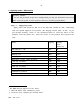
9.2 Summary of DIP switches
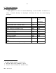
Power stage board
(2 poles DIP switch)
DIP switch OFF (UP) ON (DOWN)
DS1 60° commutation signals format 30° commutation signals format
DS2 No CFM Activate CFM
Control stage board
(9 poles DIP switch)
DIP switch ON OFF
DS1 Auto-selection of Baud rate Latch last value
DS2 Non-differential channel A Diff. input of channel A
DS3 Non-differential channel B Diff. input of channel B
DS4 Non-differential channel Ay Diff. input of channel Ay
DS5 Non-differential channel By Diff. input of channel By
DS6 Non-differential index Diff. index
DS7 Pulse/Direction format Encoder channels format
DS8 N/C
DS9 RS485 RS232
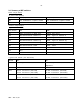
4 poles DIP switch (for Resolver)
Switch OFF ON
DS11 Tacho signal disconnected Tacho signal connected to error
amplifier.
DS12 Standard encoder resolution Non-standard encoder resolution
DS13 14 bit resolution (DS14-ON)
16 bit resolution (DS14-OFF)
10 bit resolution (DS14-ON)
12 bit resolution (DS14-OFF)
DS14 12 bit resolution (DS13-ON)
16 bit resolution (DS13-OFF)
10 bit resolution (DS13-ON)
14 bit resolution (DS13-OFF)