
- DBP SERIES USER MANUAL


88
DBP - Rev 6/93
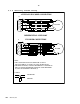
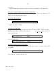
Signal input level (R193,R194)
The R/D inputs (Vin
rms
) are adjusted to the sin/cos. Resolver outputs by:
Resolver output = Vin
rms
= Vr
rms
x Transformation ratio
R193 = R194 = Vin
rms
- 2 - R
stator
(Kohm)
(R
stator
in Kohm).
When Vin
rms
<2V, install R193=R194=100 ohm.
The standard R/D converter will not operate for Vin
rms
<1.8V. Consult factory
for OEM applications.
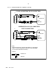
Velocity Signal
The tracking converter technique generates an internal signal at the output of
the integrator that is proportional to the rate of change of the input angle.
This dc analog output (velocity signal) is buffered and represented at terminal
H/R-12b,E-J3/23. Max output voltage is +8V.
This velocity signal can be internally connected to the summing junction of
the error amplifier by inserting R7 - see Appendix B for more details. However,
the standard procedure does not require closing the velocity loop.
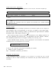
Select maximum actual velocity of the application and calculate the maximum
tracking rate T of the Resolver as follows:
T = rpm x Q / 120
T unit is rps: Resolver electrical revolution per second
Q - number of poles of Resolver ;
rpm - mechanical revolution per minute.
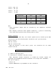
Selecting the Resolution
The resolution can be selected to be 10,12,14 or 16 bits by use of DIP
switches 13 and 14. When selecting the resolution the rps limits should not be
exceeded: