
- DBP SERIES USER MANUAL


84
DBP - Rev 6/93
7. Start - Up Procedures
7.1 Common procedures for all amplifiers types
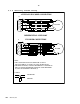
7.1.1 Commutation signals format
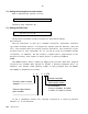
Select the position of DIP switch 1 on the upper board of the power stage
according to the commutation signal format the motor has.
DS1 positions: ON (down): 30° OFF (up): 60°
For all Resolver versions it should be 60 °.
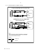
7.1.2 CFM function
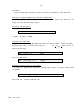
Select the position of DIP switch 2 on the upper board of the power stage
according to the motor's rated current. If it is less than 20% of the
amplifier's rated current select:
DS2 to ON (down)
Otherwise,
DS2 to OFF (up) - No CFM
7.1.3 Abort logic
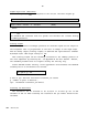
Make sure that the Abort input is connected to a High (logic) voltage
source.