
- DBP SERIES USER MANUAL


50
DBP - Rev 6/93
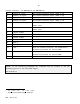
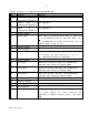
Signals connector - J8 (MBA-DBP/3U and MBA-DBP/6U)
1 Channel A output
Main encoder buffered output (20mA, 0-5V)
2 Channel -A output
Main encoder buffered output (20mA, 0-5V)
3 Channel B output
Main encoder buffered output (20mA, 0-5V)
4 Channel -B output
Main encoder buffered output (20mA, 0-5V)
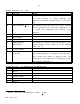
5 Encoder index output
For resolver option only buffered output
(20mA, 0-5V)
6 Encoder -index output
For resolver option only buffered output
(20mA, 0-5V)
7 Circuit common
8 Circuit common
9 Circuit common
10 Hall A
*
11 Hall B
*
12 Hall C
*
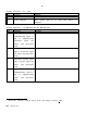
13 +15V
There are several +15V pins. The accumulative
external load should not exceed 100mA.
14 +5V output
There are several +5V pins. The accumulative
external load should not exceed 200mA.
15 Circuit common
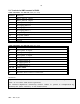
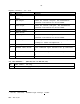
Remark: In the following paragraphs the terminals will be related to all the
mounting types as in the following sample:
H/R-2a,E-J4/13.
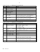
*
-1V < Vil < 1V ; 2V < Vih < 30V
Source sink capability - 2mA min.