
- DBP SERIES USER MANUAL


45
DBP - Rev 6/93
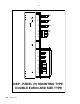
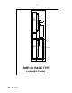
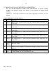
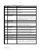
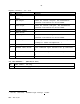
Signals connector - J3 (MBA-DBP/3U and MBA-DBP/6U)
Pin Function
Remarks
1 positive input of a
differential amplifier.
See Appendix C.
2 Negative input of a
differential amplifier.
See Appendix C.
3 Output of a
differential amplifier.
See Appendix C.
4 Circuit common
5 Analog input
This input is monitored by the main µP. When |Vi|
< 5V, R1=470ohm should be inserted. When |Vi|>
5V, R1(Kohm)=2Vi-10 should be inserted. The µP
always reads a range of +5V.
6 Circuit common
7 Circuit common
8 Current monitor
This analog output represents the actual current
in the motor. The scale (in A/V) is: Ip / 7.5
Ip - Rated peak current of amplifier.
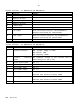
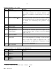
9 Circuit common
10 +5V output
There are several +5V pins. The accumulative
external load should not exceed 200mA.
11 +15V output
There are several +15V pins. The accumulative
external load should not exceed 100mA.
12 -15V output
There are several -15V pins. The accumulative
external load should not exceed 100mA.
13 Channel B output
14 Channel A output
15 Index output
For resolver option only.
16 Not connected
17 Inhibit output
Relay contact (potential free).
The relay contact is closed whenever the
amplifier is enabled. Contact rating: 0.5A, 200V,
10W.