
- DBP SERIES USER MANUAL

37
DBP - Rev 6/93
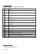
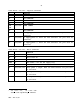
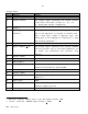
Control board - cont.
H & R Function Remarks
24a Auxiliary encoder
complementary input (-
By) or Complementary
Direction input for
Pulse and Direction
mode
24b Resolver reference
common.
The reference voltage to the resolver must be
taken from terminals 23b and 24b only.
25a +5V output
There are several +5V terminals. The accumulative
external load should not exceed 200mA.
25b Cosine signal input.
See 7.3
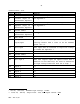
26a Circuit common
For the auxiliary encoder
26b Cosine signal common.
See 7.3
27a Channel B input
27b Sine signal input.
See 7.3
28a Channel -B input
28b Sine signal common
See 7.3
29a Channel A input
29b Circuit common
For the main encoder
30a Channel -A input
30b Index output
For resolver option only.
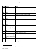
31a -Index input
31b Channel B output
32a Index input
32b Channel A output
Remark: In the following paragraphs the terminals will be related to all the
mounting types as in the following sample:
H/R-2a,E-J4/13.