
- DBP SERIES USER MANUAL

36
DBP - Rev 6/93
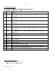
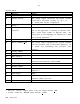
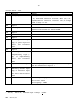
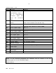
Control board - cont.
H & R Function Remarks
18a Analog input
This input is monitored by the main µP. When |Vi|
< 5V, R1=470ohm should be inserted. When |Vi|> 5V,
R1(Kohm)=2Vi-10 should be inserted. The µP always
reads a range of +5V.
18b Input 1
*
19a +5V output
There are several +5V terminals. The accumulative
external load should not exceed 200mA.
19b Input 2
*
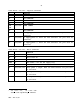
20a Circuit common
20b Input 3
*
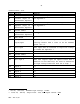
21a Auxiliary encoder input
(Ay) or pulse input for
Pulse and Direction
mode.
21b Input 4
*
22a Auxiliary encoder
complementary input (-
Ay) or complementary
Pulse and Direction
mode
22b Input 5 or Index Input.
If a homing sequence is required, the Index Input
must be connected to Input 5 *
23a Auxiliary encoder input
(By) or Direction input
for Pulse and Direction
mode
23b Resolver reference
Max. voltage: 20Vptp or 7Vrms
Max current: 80mA
Max frequency: 20KHz
*
Vil<1V, Vih>2.4V, Maximum input voltage: +30VDC