
- DBP SERIES USER MANUAL

32
DBP - Rev 6/93
5. Terminal Description
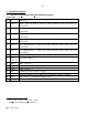
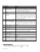
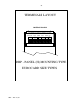
5.1 Terminals for Horizontal and Rack mounting versions
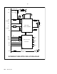
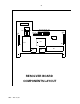
POWER BOARD - 3U size
H R Function
1 (32a,c)
Motor phase A output. With the DIN connector both pins must be
connected.
2 (30a,c
Motor phase B output. With the DIN connector both pins must be
connected.
3 (28a,c)
Motor phase C output. With the DIN connector both pins must be
connected.
4 (26a,c)
AC supply-phase A. With the DIN connector both pins must be
connected.
5 (24a,c)
AC supply-phase B. With the DIN connector both pins must be
connected.
6 (22a,c)
AC supply-phase C. With the DIN connector both pins must be
connected.
7 (20a,c)
DC power positive (+Vs)
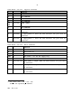
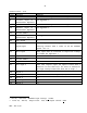
8
9
(18a,c
16a,c)
DC power common
10 (14c)
Hall sensor A
*
11 (12c)
Hall sensor B *
12 (10c)
Hall sensor C *
13 (8c)
+15VDC for Hall sensors supply.
14 (6c)
Circuit common for the Hall sensors supply (Control common).
15 (4c)
24V common - for the fan supply only.
16 (2c)
+24VDC, 400mA for use with brushless fan
*
-1V < Vil < 1V ; 2V < Vih < 30V
Source sink capability - 2mA min.