Tuba Digital Servo Drive Installation Guide April 2008 (Ver. 1.3) www.elmomc.
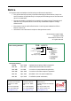
Notice This guide is delivered subject to the following conditions and restrictions: This guide contains proprietary information belonging to Elmo Motion Control Ltd. Such information is supplied solely for the purpose of assisting users of the Tuba servo drive in its installation. The text and graphics included in this manual are for the purpose of illustration and reference only. The specifications on which they are based are subject to change without notice.
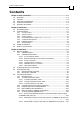
Tuba Installation Guide MAN-TUBIG (Ver. 1.3) Contents Chapter 1: Safety Information ............................................................................................... 1-1 1.1 Warnings.................................................................................................................... 1-2 1.2 Cautions ..................................................................................................................... 1-2 1.3 Directives and Standards ..............................
Tuba Installation Guide Contents MAN-TUBIG (Ver. 1.3) 3.4.7.4 Pulse-and-Direction Input Option on FEEDBACK B (YA[4]=0) .......... 3-31 3.4.8 I/O Cables.............................................................................................................. 3-33 3.4.8.1 Analog Inputs............................................................................................ 3-33 3.4.8.2 Digital Inputs (on GENERAL I/O Port) ................................................. 3-34 3.4.8.
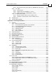
Tuba Installation Guide Contents MAN-TUBIG (Ver. 1.3) A.14.7 Packing .................................................................................................................. A-18 A.14.8 Environmental...................................................................................................... A-18 Index ..........................................................................................................................................
Tuba Installation Guide MAN-TUBIG (Ver. 1.3) Chapter 1: Safety Information In order to achieve the optimum, safe operation of the Tuba servo drive, it is imperative that you implement the safety procedures included in this installation guide. This information is provided to protect you and to keep your work area safe when operating the Tuba and accompanying equipment. Please read this chapter carefully before you begin the installation process.
Tuba Installation Guide Safety Information MAN-TUBIG (Ver. 1.3) 1.1 Warnings To avoid electric arcing and hazards to personnel and electrical contacts, never connect/disconnect the servo drive while the power source is on. Power cables can carry a high voltage, even when the motor is not in motion. Disconnect the Tuba from all voltage sources before it is opened for servicing. The Tuba servo drive contains grounding conduits for electric current protection.
Tuba Installation Guide Safety Information MAN-TUBIG (Ver. 1.3) 1.
Tuba Installation Guide MAN-TUBIG (Ver. 1.3) Chapter 2: Introduction This installation guide describes the Tuba servo drive and the steps for its wiring, installation and powering up. Following these guidelines ensures maximum functionality of the drive and the system to which it is connected. 2.
Tuba Installation Guide Introduction MAN-TUBIG (Ver. 1.3) 2.2.3 Position Control Programmable PIP control filter Programmable notch and low-pass filters Position follower mode for monitoring the motion of the slave axis relative to a master axis, via an auxiliary encoder input Pulse-and-direction inputs Sample time: four times that of current loop Fast event capturing inputs 2.2.
Tuba Installation Guide Introduction MAN-TUBIG (Ver. 1.3) 2.2.
Tuba Installation Guide Introduction MAN-TUBIG (Ver. 1.3) 2.4 How to Use this Guide In order to install and operate your Elmo Tuba servo drive, you will use this manual in conjunction with a set of Elmo documentation.
Tuba Installation Guide 3-1 MAN-TUBIG (Ver. 1.3) Chapter 3: Installation 3.1 Before You Begin 3.1.1 Site Requirements You can guarantee the safe operation of the Tuba by ensuring that it is installed in an appropriate environment. Feature Value Ambient operating temperature 0 °C – 40 °C (32 °F – 104 °F) Maximum relative humidity 90% non-condensing Operating area atmosphere No flammable gases or vapors permitted in area Models for extended environmental conditions are available.
Tuba Installation Guide Installation MAN-TUBIG (Ver. 1.3) 3.1.2.3 Power Connectors Component External DC Link Cable Main Power Cable Motor Cable Auxiliary Power Cable 3.1.2.4 Connector Described in Section B1, B2 on External DC Link Cable 3.4.2.3 3.4.2.2 PE, AC1, AC2, and AC3 on Power Connector M1, M2, M3, PE on Power Connector 24v Photo 3.4.2.
Tuba Installation Guide Installation MAN-TUBIG (Ver. 1.3) 3.1.2.5 Feedback and I/O Connectors Component Analog Inputs (if needed) Port on Tuba Described in Section ANALOG I/O 3.4.8.1 Diagram CEL0040A-DWG COR016A Digital Outputs Cable (if needed) COMMITTED I/O 3.4.8.2 Digital Inputs Cable (if needed) GENERAL I/O Main Feedback Cable FEEDBACK A 3.4.5 Auxiliary Feedback Cable (if needed) FEEDBACK B 3.4.7 3.4.8.
Tuba Installation Guide Installation MAN-TUBIG (Ver. 1.3) 3.1.2.6 3-4 Other Items Needed Component Described in Section Diagram PC for drive setup and tuning Motor data sheet or manual 3.2 Unpacking the Drive Components Before you begin working with the Tuba system, verify that you have all of its components, as follows: The Tuba servo drive The Composer software and software manual The Tuba is shipped in a cardboard box with styrofoam protection. To unpack the Tuba: 1.
Tuba Installation Guide Installation MAN-TUBIG (Ver. 1.3) 3.3 3-5 Mounting the Tuba The Tuba has been designed for two standard mounting options: Attaching directly to the wall with screws Mounting on a DIN rail With either type of mounting, be sure to leave about 10 cm (4 in) above and below the instrument for heat dissipation. 3.3.1 Mounting Directly onto Wall The vertical mounting strip at the back of the Tuba enables you to screw the drive directly into a wall.
Tuba Installation Guide Installation MAN-TUBIG (Ver. 1.3) 3.3.2 Mounting on a DIN Rail At the top rear of the Tuba, a horizontal groove lets you quickly and easily snap the drive onto a DIN rail in your work area. To mount the Tuba on a DIN rail: 2. Be sure that the vertical mounting strip (with the hole at the top) is pressed down fully and does not protrude from the top of the instrument. Figure 3-2: Mounting Strip Pressed Down Tilt the Tuba back towards the top part of the DIN rail.
Tuba Installation Guide Installation MAN-TUBIG (Ver. 1.3) 3-7 Press the Tuba down to a vertical position until it clicks onto the DIN rail. Figure 3-4: Tuba Mounted on DIN Rail 3.4 Connecting the Cables 3.4.1 Wiring the Tuba Once the Tuba is mounted, you are ready to wire the device. Proper wiring, grounding and shielding are essential for ensuring safe, immune and optimal servo performance of the Tuba.
Tuba Installation Guide Installation MAN-TUBIG (Ver. 1.3) 3-8 Keep the motor wires as far away as possible from the feedback, control and communication cables. Ensure that in normal operating conditions, the shielded wires and drain carry no current.
Tuba Installation Guide Installation MAN-TUBIG (Ver. 1.
Tuba Installation Guide Installation MAN-TUBIG (Ver. 1.3) 3.4.
Tuba Installation Guide Installation MAN-TUBIG (Ver. 1.3) 3.4.2.1 3-11 Connecting the Motor Cable Connect the motor power cable to the M1, M2, M3 and PE terminals of the main power connector. The phase connection order is arbitrary because the Composer will establish the proper commutation automatically during setup. However, if you plan to copy the set-up to other drives, then the phase order on all copy drives must be the same.
Tuba Installation Guide Installation MAN-TUBIG (Ver. 1.3) 3.4.2.2 3-12 Connecting the Main Power Cable Connect the main power supply cable to the AC1, AC2 and AC3 terminals of the main power connector. Connect the Protective Earth wire to the nearest PE terminal on the terminal block. Notes for connecting the AC power cable: For best noise immunity, a shielded (not twisted) cable is recommended (not mandatory) for the AC power supply cable. A 4-wire shielded cable should be used.
Tuba Installation Guide Installation MAN-TUBIG (Ver. 1.3) 3.4.3 3-13 Connecting the Auxiliary Supply Cable (24v) Connect the auxiliary supply to the 24VDC terminal block on the bottom of the Tuba. Remember, you are working with DC power; so be sure to exercise caution. Notes for 24 VDC auxiliary supply connections: Use a 24 AWG twisted pair shielded cable. For best results the shield should have aluminum foil covered by copper braid.
Tuba Installation Guide Installation MAN-TUBIG (Ver. 1.3) 3.4.4 3-14 Feedback and Control Cable Assemblies The Tuba features easy-to-use D-sub type connections for all Control and Feedback cables. Below are instructions and diagrams describing how to assemble those cables. Use 24, 26 or 28 AWG twisted-pair shielded cables (24 AWG cable is recommended). For best results, the shield should have aluminum foil covered by copper braid. Use only a D-sub connector with a metal housing.
Tuba Installation Guide Installation MAN-TUBIG (Ver. 1.3) 3.4.5 3-15 Main Feedback Cable (Feedback A) The main feedback cable is used to transfer feedback data from the motor to the drive.
Tuba Installation Guide Installation MAN-TUBIG (Ver. 1.
Tuba Installation Guide Installation MAN-TUBIG (Ver. 1.
Tuba Installation Guide Installation MAN-TUBIG (Ver. 1.
Tuba Installation Guide Installation MAN-TUBIG (Ver. 1.
Tuba Installation Guide Installation MAN-TUBIG (Ver. 1.
Tuba Installation Guide Installation MAN-TUBIG (Ver. 1.
Tuba Installation Guide Installation MAN-TUBIG (Ver. 1.
Tuba Installation Guide Installation MAN-TUBIG (Ver. 1.3) 3.4.6 3-23 Main and Auxiliary Feedback Combinations The Main Feedback is always used in motion control devices whereas Auxiliary Feedback is often, but not always used. The Auxiliary Feedback connector on the Tuba, “FEEDBACK B” has two ports, Port B1 and Port B2.
Tuba Installation Guide Installation MAN-TUBIG (Ver. 1.
Tuba Installation Guide Installation 3-25 MAN-TUBIG (Ver. 1.3) 3.4.7 Auxiliary Feedback (FEEDBACK B) When using one of the auxiliary feedback options, the relevant functionality of FEEDBACK B ports are software selected for that option. Refer to the Tuba Command Reference Manual for detailed information about FEEDBACK B setup. 3.4.7.
Tuba Installation Guide Installation MAN-TUBIG (Ver. 1.
Tuba Installation Guide Installation MAN-TUBIG (Ver. 1.3) 3.4.7.2 3-27 Differential Auxiliary Encoder Input Option on FEEDBACK B (YA[4]=2) The Tuba can be used as a slave by receiving the position of the master encoder data (on Port B1) in Follower or ECAM mode. In this mode Port B2 provides differential buffered auxiliary outputs for the next slave axis in follower or ECAM mode.
Tuba Installation Guide Installation MAN-TUBIG (Ver. 1.
Tuba Installation Guide Installation 3-29 MAN-TUBIG (Ver. 1.3) 3.4.7.3 Single-ended Auxiliary Input Option on FEEDBACK B (YA[4]=2) The Tuba can be used as a slave by receiving the position data of the master encoder (on Port B1) in Follower or ECAM mode. In this mode Port B2 provides differential buffered auxiliary outputs for the next slave axis in Follower or ECAM mode.
Tuba Installation Guide Installation MAN-TUBIG (Ver. 1.
Tuba Installation Guide Installation MAN-TUBIG (Ver. 1.3) 3.4.7.4 3-31 Pulse-and-Direction Input Option on FEEDBACK B (YA[4]=0) This mode is used for input of differential or single-ended pulse-and-direction position commands on Port B1. In this mode Port B2 provides differential buffered pulse-anddirection outputs for another axis.
Tuba Installation Guide Installation MAN-TUBIG (Ver. 1.
Tuba Installation Guide Installation 3-33 MAN-TUBIG (Ver. 1.3) 3.4.8 I/O Cables The Tuba has three I/O ports (ANALOG INPUTS, DIGITAL INPUTS AND DIGITAL OUTPUTS) which can be used to connect 2 analog inputs, 10 separate digital inputs and 6 separate digital outputs: LABEL ANALOG INPUTS GENERAL I/O COMMITTED I/O Total Analog Input 2 - - 2 Digital Input - 10 - 10 Digital Output - - 6 6 I/O 3.4.8.
Tuba Installation Guide Installation MAN-TUBIG (Ver. 1.3) 3.4.8.2 3-34 Digital Inputs (on GENERAL I/O Port) The Tuba servo drive is equipped with a 25-pin D-sub plug for digital inputs. When assembling an I/O cable for digital input follow the instructions in Section 3.4.4 (Feedback and Control Cable Assemblies) using a 25-pin D-sub socket with a metal case. The pins are described below. Pin Signal Function 1 N.C.
Tuba Installation Guide Installation MAN-TUBIG (Ver. 1.
Tuba Installation Guide Installation MAN-TUBIG (Ver. 1.3) 3.4.8.3 3-36 Digital Outputs (on COMMITTED I/O Port) The Tuba servo drive is equipped with a 15-pin, high-density, D-sub socket for digital outputs. When assembling an I/O cable for digital outputs follow the instructions in Section 3.4.4 (Feedback and Control Cable Assemblies) using a 15-pin high density D-sub plug with a metal case. The pins are described below.
Tuba Installation Guide Installation MAN-TUBIG (Ver. 1.
Tuba Installation Guide Installation MAN-TUBIG (Ver. 1.3) 3.4.9 3-38 Communication Cables The communication cables use an 8-pin RJ-45 plug that connect to the RS-232 and CANopen ports on the front of the Tuba. The communication interface may differ according to the user’s hardware. The Tuba can communicate using the following options: a. RS-232, full duplex b. CANopen RS-232 communication requires a standard, commercial 3-core null-modem cable connected from the Tuba to a serial interface on the PC.
Tuba Installation Guide Installation MAN-TUBIG (Ver. 1.3) 3-39 Only one RS-232 port can be used at a time. Figure 3-30: RS-232 Connection Diagram 3.4.9.2 CANopen Communication (on the COMM.2 Ports) Notes for connecting the CANopen communication cable: Use 26 or 28 AWG twisted pair shielded cables. For best results, the shield should have aluminum foil and covered by copper braid with a drain wire Connect the shield to the ground of the host (PC).
Tuba Installation Guide Installation MAN-TUBIG (Ver. 1.
Tuba Installation Guide Installation MAN-TUBIG (Ver. 1.3) 3.5 3-41 Powering Up After the Tuba has been mounted, check that the cables are intact. The Tuba servo drive is then ready to be powered up. Caution: Before applying power, ensure that the AC supply is within the range specified for your specific type of Tuba. 3.6 Initializing the System After the Tuba has been connected and mounted, the system must be set up and initialized.
Tuba Installation Guide MAN-TUBIG (Ver. 1.3) Appendix: Technical Specifications A.1 A.1.1 Features Motion Control Modes • Current/Torque - up to 14 kHz sampling rate • Velocity up to 7 kHz sampling rate • Position up to 3.5 kHz sampling rate A.1.2 Advanced Positioning Motion Control Modes • PTP, PT, PVT, ECAM, Follower, Pulse and Direction, Dual Loop • Fast event capturing inputs • Fast output compare (OC) A.1.3 Advanced Filters and Gain Scheduling • • • • A.1.
Tuba Installation Guide Technical Specifications MAN-TUBIG (Ver. 1.3) A.1.
Tuba Installation Guide Technical Specifications MAN-TUBIG (Ver. 1.3) A.
Tuba Installation Guide Technical Specifications MAN-TUBIG (Ver. 1.3) A.3 Mounting Dimensions Rear View A.4 Mechanical Specifications Feature Details Mounting Method Wall Mount ("Bookshelf") DIN Rail Overall Dimensions 247 x 190 x 92 mm (9.7" x 7.5" x 3.6") Weight 2.7 kg (5.
Tuba Installation Guide Technical Specifications MAN-TUBIG (Ver. 1.3) A.
Tuba Installation Guide Technical Specifications A-6 MAN-TUBIG (Ver. 1.3) A.7 Tuba Connections The following connectors are used for wiring the Tuba. Pins Type 5 Motor 2 Ground 3 Power 2 DC Link 2 Auxiliary Power Maker & Part No. Port M1, M2, M3 PE, PE 10 pole 8 mm pitch Molex terminal block AC1, AC2, AC3 B1, B2 2 pole 0.325” (8 mm) pitch Molex terminal strip +, - (24V) Connector Location Auxiliary Power Motor Ground Power Ext.
Tuba Installation Guide Technical Specifications MAN-TUBIG (Ver. 1.3) A.7.1 Auxiliary Supply Feature Details Auxiliary power supply DC source only Auxiliary supply input voltage 24 V +15% Auxiliary supply input power 20 W The Tuba CANNOT operate without a 24 Volt Auxiliary Power Supply Be sure to maintain power within the 24 V +15% range as higher voltages will damage the fan. A.8 Control Specifications A.8.
Tuba Installation Guide Technical Specifications MAN-TUBIG (Ver. 1.3) A.8.
Tuba Installation Guide Technical Specifications MAN-TUBIG (Ver. 1.3) A.9 Feedbacks A.9.1 Feedback Supply Voltage Feature Details Main encoder supply voltage 5 V +5% @ 200 mA maximum Auxiliary encoder supply voltage 5 V +5% @ 200 mA maximum A.9.
Tuba Installation Guide Technical Specifications MAN-TUBIG (Ver. 1.3) A.9.3 Digital Halls Feature Details Halls inputs H A , H B, H C . Single ended inputs Built in hysteresis for noise immunity. Input voltage Nominal operating range: Maximum absolute: High level input voltage: Low level input voltage: 0 V < VIn_Hall < 5 V -1 V < VIn_Hall < 15 V VInHigh > 2.5 V VInLow < 1 V Input current Sink current (when input pulled to the common): 3mA Source current: 1.
Tuba Installation Guide Technical Specifications MAN-TUBIG (Ver. 1.3) A.9.5 Resolver Feature Details Resolver format Input resistance Differential 2.49 kΩ Resolution Programmable: 10 ~ 15 bits Maximum electrical frequency (RPS) 512 revolutions/sec Resolver transfer ratio 0.5 Reference frequency 1/Ts (Ts = sample time in seconds) Reference voltage Supplied by the Tuba Reference current Up to ±50 mA A.9.
Tuba Installation Guide Technical Specifications MAN-TUBIG (Ver. 1.3) A.9.7 Potentiometer Feature Details Potentiometer Format Single-ended Operating Voltage Range 0 ~ 5 V supplied by the Tuba Potentiometer Resistance 100 Ω ~ 1 kΩ … above this range, linearity may be affected detrimentally Input Resistance 100 kΩ Resolution 14 Bit A.9.
Tuba Installation Guide Technical Specifications MAN-TUBIG (Ver. 1.3) A-13 A.10 I/Os The Tuba has: A.10.1 10 Digital Inputs 6 Digital Outputs 2 Analog Inputs Digital Input Interfaces (on GENERAL I/O port) Feature Details Type of input Input current Optically isolated Single ended PLC level Iin = Connector Location DIGITAL INPUTS Vin − 6.5V 2500Ω * Iin = 2.2 mA @ Vin = 12 V Input current for high speed inputs 5 & 6 Iin = Vin − 6.5V 1250Ω * Iin = 4.
Tuba Installation Guide Technical Specifications MAN-TUBIG (Ver. 1.3) A.10.2 A-14 Digital Output Interface (on COMMITTED I/O port) Feature Details Type of output Optically isolated Open collector and open emitter Maximum supply output (Vcc) 30 V Max. output current Iout (max) (Vout = Low) Iout (max) ≤ 15 mA VOL at maximum output voltage (low level) Vout (on) ≤ 0.3 V + 0.02 * Iout (mA) RL External resistor RL must be selected to limit output current to no more than 15 mA.
Tuba Installation Guide Technical Specifications MAN-TUBIG (Ver. 1.3) A-15 A.10.3 Analog Input Feature Details Maximum operating differential voltage ± 10 V Maximum absolute differential input voltage ± 16 V Differential input resistance 3 kΩ Analog input command resolution 14-bit Analog Input A.
Tuba Installation Guide Technical Specifications MAN-TUBIG (Ver. 1.3) A-16 A.12 Pulse Width Modulation (PWM) Feature Details PWM resolution 12-bit PWM switching frequency on the load 2/Ts (factory default 22 kHz on the motor) A.13 Single-phase Operation When operating with a single-phase supply (TUB-x/230 only), the voltage drop must be considered. Voltage drop can be calculated using the following equation: Vout (Max Phase to phase) = 0.
Tuba Installation Guide Technical Specifications MAN-TUBIG (Ver. 1.3) A-17 A.14 Standards Compliance A.14.1 Quality Assurance Specification Details ISO 9001:2000 Quality Management A.14.2 Design Specification Details MIL-HDBK- 217F Reliability prediction of electronic equipment (rating, de-rating, stress, etc.) IPC-D-275 IPC-SM-782 IPC-CM-770 Printed wiring for electronic equipment (clearance, creepage, spacing, conductors sizing, etc.
Tuba Installation Guide Technical Specifications MAN-TUBIG (Ver. 1.3) A.14.6 PCB Specification Details In compliance with IPC-A-600, level 2 Acceptability of printed circuit boards A.14.7 A-18 Packing Specification Details In compliance with EN100015 Protection of electrostatic sensitive devices A.14.
Tuba Installation Guide I-1 MAN-TUBIG (Ver. 1.
Tuba Installation Guide Index MAN-TUBIG (Ver. 1.
Tuba Installation Guide Index MAN-TUBIG (Ver. 1.