Integrated High Speed Dome Camera ESD-370 Indoor Dome User’s Manual
User’s Manual Notice The information given in this manual was current when published. The company reserves the right to revise and improve its products. All specifications are subject to change without notice. Copyright Under copyright laws, the contents of this user manual may not be copied, photocopied, translated, reproduced or reduced to any electronic medium or machine-readable format, in whole or in part, without prior written permission of the company.
User’s Manual Cautions • Handle the camera carefully Do not abuse the camera. Avoid striking, shaking, etc. The camera could be damaged by improper handing or storage. • Do not disassemble the camera To prevent electric shock, do not remove screws or covers. There are no user serviceable parts inside. Ask a qualified service person for servicing. • Do not block cooling holes on the bracket This camera has a cooling fan inside.
User’s Manual Content 1. Overview .................................................................................................................................... 5 1.1 Product Features............................................................................................................. 6 1.2 Product Application ......................................................................................................... 7 2. Connecting the High Speed Dome ........................................
User’s Manual 3.3.13 HOME SETTING ............................................................................................. 27 3.3.14 SEQUENCE .................................................................................................... 29 3.3.15 AUTOPAN........................................................................................................ 30 3.3.16 CRUISE ........................................................................................................... 32 3.3.
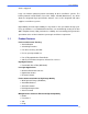
User’s Manual 1. Overview ESD-370 is a new subcompact integrated high speed dome camera designed to deliver superb performance and durability with an intelligent and stylish housing that is suitable in any security and surveillance installation. ESD-370 series dome cameras support one cabling for easy installation, and can be integrated with CCTV products, such as DVRs, Control Keyboards, and CCTV accessories for a total surveillance solution.
User’s Manual alarm is triggered. Large set of built-in protocols provide connectivity to other surveillance systems. The built-in protocols include ELMO, Pelco, VCL, Philips, AD-422 (Manchester), etc, which allow the Integrated High Speed Dome Camera series to be integrated with other suppliers' surveillance systems. Dependability and ultra high reliability are key factors in the speed dome design cycle.
User’s Manual • AD/AD-422 • Chiper Privacy Mask for Privacy Protection • Up to 24 privacy zones of camera view programmable Dynamic Dome Configuration • Flexible In/Outdoor mountings • Compact lightweight design for easy installation • Weather resistant housing for temperature, sun ray, and rain Integrated with Web, Enhanced Internet Capability (Optional) • Remote monitoring operation/system configuration/software upgrade • Include Window active applications 1.
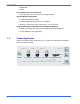
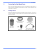
User’s Manual 2. Connecting the High Speed Dome Please refer to the following sections to connect, set and operate the dome camera. In order to control the integrated high speed dome, basically a control keyboard or other control device is required. 2.1 Package Content Before proceeding, please check the box contains the items listed here. If any item is missing, or if damage is evident, DO NOT install or operate the product and contact your dealer for assistance.
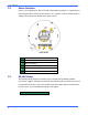
User’s Manual 2.2 Switch Definition First of all, configuring the dome ID and communication protocol is required before connecting the dome camera to other devices. The switches used for configuring these settings are located on the bottom of the dome camera. Indoor Dome 2.
User’s Manual Half-duplex 2.4 Full-duplex Pin 3 Termination Pin 4 Line Lock Pin 5 Set Factory Default Pin 6 Reserved Dome ID Setting Use the switch to change your speed dome ID by turning the arrow to the desired number respectively. For instance, if the dome ID is 123, the ID switch should be set as below. NOTE: No two domes should be given the same ID, or communication conflict may occur.
User’s Manual ELMO AD422 DM P Pelco D Pelco D Pelco P Pelco P JVC GANZ 07 08 09 11 12 13 14 15 16 9600 4800 9600 4800 9600 2400 9600 9600 9600 Select protocol: Pelco D, for instance, the ID switch should be set as below. Decimal 2.6 single digit 22-Pin Connector Definition A 50-cm data cable (as belowing figure) is shipped with the integrated high speed dome for a quick installation for demo or testing usage. The 22-pin connector definition is listed as below. No.
User’s Manual 7 T+ Yellow 8 R- Orange 9 T- Green 10 R+ Brown 11~20 1007 24AWG Alarm Pin (Not wired) 21 VGND 22 Video 12
User’s Manual 2.7 Alarm Pin Definition The alarm pins are serviceable for connecting alarm in- and output devices. Following lists the definition of alarm pin on the 22-pin connector located on the bottom of the dome camera. 2.
User’s Manual 3. Operation and Configuration 3.1 OSD Display Format The information shown on the screen are described in terms of OSD display, position and function description in the table below.
User’s Manual 3.2 OSD Menu Tree The OSD setup menu structure of S and DR models are listed below. The star symbol indicates the factory default. For detailed function description, please see section 3.3 Configuration Menu.
User’s Manual Item HOME SETTING SEQUENCE AUTOPAN CRUISE Layer 1 Layer 2 PRESET POINT SEQUENCE LINE AUTOPAN LINE CRUISE LINE <001> ~ <256> <1> ~ <8> <1> ~ <4> <1> DWELL TIME EXIT HOME FUNC. SELECT MODE <001> ~ <127> Sec., ALWAYS YES , PRESET PRESET POINT SEQUENCE LINE AUTOPAN LINE CRUISE LINE RETURN TIME GO EXIT SEQUENCE LINE SEQUENCE POINT PRESET POS.
User’s Manual Item TIME Layer 1 Layer 2 MASK CLEAR+RESET MASK DSIPLAY EXIT TIME DISPLAY SET YEAR SET MONTH SET DAY SET HOUR SET MINUTE EXIT+SAVE SCHEDULE SWITCH SCHEDULE POINT SCHEDULE HOUR SCHEDULE MIN SCHEDULE MODE <01> ~< 08> 17 , <01> ~ <32> NONE PRESET SEQUENCE AUTOPAN CRUISE IR FUNC.
User’s Manual 3.3 Configuration Menu The detailed functions and parameter settings of your high speed dome can be set by the OSD (On Screen Display) menu with a control device, such as ELMO control keyboard. The functions in OSD menu are described in the following sections.
User’s Manual camera parameters. 3.3.2 BACKLIGHT The Backlight compensation function prevents the center object from being too dark in surroundings where excessive light is behind the center object. The Backlight Compensation Level ranges from 000 to 100. BLC LEVEL LEVEL EXIT 20 YES NOTE: If this function is enabled, the WDR function (for DR model only) will be disabled automatically. For details, refer to section 3.3.19 WDR Setting. 3.3.
User’s Manual function, users can adjust the enhancement of the edges of objects in the picture. When shooting text, this function may help by making them sharper and achieve a better image. There are 32 levels of adjustment; the options are <00> ~ <31>, <00> represents “no enhancement”. • AUTO The dome camera will assign a proper aperture value automatically for camera to achieve a better image. • MANUAL Select this item if you want to adjust aperture value manually.
User’s Manual depends on the AGC circuit. • AGC With this option, the AGC priority is higher than SHUTTER and IRIS; SHUTTER and IRIS circuit will function automatically in cooperating with AGC to get consistent exposure. If AGC is adjusted manually, the exposure compensation depends on the changing of IRIS. 3.3.6 WBC MODE A digital camera needs to find reference color temperature, which is a way of measuring the quality of a light source, for calculating all the other colors.
User’s Manual • ON Display the ID address of the selected dome on the right bottom of the monitor screen. • OFF Hide the ID address of the selected dome. 3.3.8 SETUP MENU Users can adjust camera lens model parameters under SETUP MENUs. Depending on the model of dome cameras, the SETUP MENUs are different. E/F/U Model SETUP MENU1 FLIP ZOOM SPEED SPEED BY ZOOM AUTO CALI.
User’s Manual IMAGE represents digital IMAGE FLIP, enables users to keep tracking object seamlessly and no delay occurs in comparing with mechanical flip. NOTE: The Privacy Mask function will be automatically disabled if the Image Flip function is enabled, and “Masking will be disabled” will be displayed on the screen. M.E. The item is a standard mechanical operation. As the dome tilts 90°, it will pan 180°, then continuing tilt to keep tracking object. OFF Select this item to disable the flip function.
User’s Manual resolution of the zoomed image quality. On the other hand, Digital zoom takes a portion of image and expands that image to the full size of the image; however the image quality will be reduced. Digital zoom ratio is adjustable from <1> to <12>. • SLOW SHUTTER The shutter speed determines how long the image sensor is exposed to light. To see clear image in a dark environment, enable this function and select a slower shutter speed. The shutter speed is adjustable on DR model.
User’s Manual 3.3.10 TITLE DISPLAY Users are allowed to name a certain view area and display its title for easy recognition. At this item, users can choose to display or not to display the titles set in advance. • ON A title set for certain view will be displayed when the dome back to the view area. • OFF When the TITLE DISPLAY is set , no title will be displayed on the screen even titles are set in advance. 3.3.
User’s Manual and press to delete the selected character. STEP7: When the setting is completed, move the cursor to and press to save. 3.3.12 ALARM SETTING The integrated high speed dome provides eight alarm inputs and two alarm outputs (N.O. and N.C) to connect alarm devices. With this function, dome will cooperates with alarm system to catch the event images. For wiring, please refer to the installation guide and/or qualified service personnel.
User’s Manual • ALARM ACTION Select one of these modes that choose a kind of actions that should be executed when an alarm is triggered. The alarm actions can be set to execute the preset position, sequence, auto-pan or cruise function. Use the right direction key of the control keyboard to change the setting, and the bellowing items will change in cooperating with your selection. • PRESET Select a preset point where the dome should go when an alarm pin is triggered.
User’s Manual stops or missing events. HOME SETTING HOME FUNCTION SELECT MODE PRESET POINT RETURN TIME GO EXIT • OFF PRESET 001 001 ENTER YES HOME FUNCTION The item is used to enable or disable the HOME function. Use the left/right direction keys of the control keyboard to change the setting. • SELECT MODE Select one of the modes that the dome should execute when HOME function is enabled and the RETURN TIME is up. The options are , , and .
User’s Manual manually by selecting this item. • EXIT Exit the HOME SETTING menu. 3.3.14 SEQUENCE The function executes pre-positioning of the pan, tilt, zoom and focus features in a certain sequence for a camera. Before set up this function, users must setup at least two preset points. SEQUENCE SEQUENCE LINE SEQUENCE POINT PRESET POSITION SPEED DWELL TIME RUN SEQUENCE EXIT • 1 01 001 1 001 ENTER YES SEQUENCE LINE There are eight sets of sequence lines built in the dome camera.
User’s Manual Speed 4 Speed 5 Speed 6 Speed 7 Speed 8 Speed 9 Speed 10 Speed 11 Speed 12 Speed 13 Speed 14 Speed 15 • 45 55 65 75 185 205 225 250 280 320 365 400 30 40 50 58 185 210 240 275 305 335 365 400 DWELL TIME The DWELL TIME is the duration time that the dome will stay at the sequence point, and the range is from <0> to <127> seconds. The dome will go to the next sequence point when the DWELL TIME is up.
User’s Manual as endpoint. • START POINT Follow the description to set the start position of the AUTOPAN path. 1. Move the cursor to and press while item flashes, the item will turn automatically. 2. Move the dome to a desired position and press to save the position as the start point; the cursor will move to automatically. Ensure to set the end point to complete the auto-pan setting.
User’s Manual • Speed 3 35 Speed 4 45 RUN AUTOPAN After the setting is completed, select this item to manually execute the Auto-pan function. • EXIT Exit the AUTOPAN setup menu. 3.3.16 CRUISE A Cruise is a route of manual operations that can be stored and recalled to execute repeatedly. It can be formed of pan, tilt position. CRUISE RECORD START RECORD END RUN CRUISE EXIT • ENTER ENTER ENTER YES RECORD START Follow the description to record the CRUISE path. 1.
User’s Manual 3.3.17 IR FUNCTION (Removable IR Cut) With the IR cut filter, the dome can still catch clear image at night time or very dark light condition. During day time, the IR cut filter will be on to block the infrared light for clear image; during night time, the IR cut filter will be removed to catch infrared light to view images in black and white. Only with DR model, users are able to view color images when the IR function activated.
User’s Manual function is enabled, because the WDR function has better effect than the Backlight compensation. WDR SETTING WDR SWITCH WDR FUNCTION EXIT • OFF AUTO YES WDR SWITCH Enable or disable the WDR function with the item. • WDR FUNCTION This item is used to define the WDR function mode. AUTO If select , the dome camera operates the WDR function automatically. MANUAL Users are allowed to adjust WDR function manually by defining the RATIO LEVEL, SHUTTER SPEED and IRIS OFFSET value.
User’s Manual PRIVACY PRIVACY SWITCH SHADE SET MASK MASK CLEAR+RESET MASK DISPLAY EXIT • ON GRAY 01 01 FIRST YES PRIVACY SWITCH The item is used to enable or disable masking function. Set this item to before configuring mask zone. • SHADE The color of privacy mask can be selected through this item. The available colors are black, gray and white. • SET MASK After pressing on this item, dome will memorize this position as privacy mask position, up to 8 masks can be set.
User’s Manual • MASK CLEAR+RESET The item is used to clear the mask settings of the selected privacy mask. Use LEFT/RIGHT direction keys to select a mask and press to erase its configuration. • MASK DISPLAY This item is used to set the occasion to display privacy mask. FIRST If select this mode, the camera will detect the mask zone of the next preset position and display the mask in advance, then pan the dome to the preset point.
User’s Manual • HOUR / MINUTE The items are for setting up the system time. • EXIT+SAVE Exit this page. 3.3.22 SCHEDULE FUNCTION The unique Scheduling function enables users to program a preset point or function (Sequence/Auto-pan/Cruise) automatically actions in certain period of time.
User’s Manual Enable the Cruise function for the selected schedule. IR FUNCTION Select or to enable the function for the schedule. 3.3.23 EXIT OSD To exit the OSD setup menu, users can either select this item, or press the ESC button on control keyboard quickly.
User’s Manual Appendix A: Technical Specification All specifications are subject to change without notice.
User’s Manual resolutions. Standard Resolution: 768 steps/circle. GENERAL Environment Controller Interface Operating Temperature Dimension Weight Power Source Power Consumption Regulatory High Resolution: 1600 steps/circle Indoor RS-485 0°C~40°C (32°F~104°F) ∅131×226mm (5.2x7.6 Inches) 1.6kg (3.
User’s Manual OSD Menu Notes The following OSD menu tables are provided for users to record the dome settings. Item DEFAULT CAMERA BACKLIGHT FOCUS APERTURE AE MODE WBC MODE ID DISPLAY SETUP MENU TITLE DISPLAY TITLE SETTING Layer 1 , ON OFF AUTO MANUAL AUTO MANUAL AUTO SHUTTER IRIS AGC AUTO MANUAL , FLIP ZOOM SPEED SPEED BY ZOOM AUTO CALI.
User’s Manual Item AUTOPAN CRUISE Layer 1 SEQUENCE POINT PRESET POS.
ELMO USA Corp. 1478 Old Country Rd.