
User's Manual


HARSFEN0602
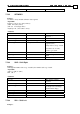
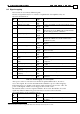
Integer revolution, with origin at the electrical angle of
zero.
21 Filtered torque command Short The command to the Q current controller, at the
output of the command filter.
45 Motor DC supply voltage Short Sample Motor DC supply voltage.
64 External position reference Long -
Integer
The part of the position reference generated by
external inputs.
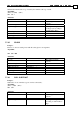
Table 8-3: Some additional recorded signals
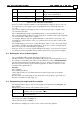
Before recording a signal from Table 8-3, this signal must be "mapped to the recorder". In
the mapping process, the signal is given a logical ID that can be referred directly by the
recorder.
Up to sixteen signals may be mapped to the recorder at any time. Up to 8 signals can be
recorded at the same time.
The command RV[N]=x maps a signal with the ID of x to the logical ID of N, N=1..16.
RC is a bit field parameter (bit 0 to 15) that signals the recorder the actual required signal. In
our case the bit N-1 of RC points to signal x.
For example, RV[2]=1 maps the signal with the ID of 1 (the main encoder speed) to the
logical ID of 2. It means that in order to record the main encoder speed bit 1 of RC should
be set (RC=2).
The default mapping, restored at boot, maps the signals of ID's 1 to 16 to the corresponding
logical ID's 1..16. Thus the signals with the ID's 1..16 can be recorded by using the logical
ID's 1..16 respectively, without further programming.
If the user desires to record only signals with ID's in the range 1..16, he need not be aware to
the difference between signal ID's and logical ID's, and he need not program any mapping.
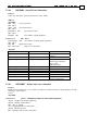
8.3 Defining the set of recorded signals
The command RC defines which of the mapped signals to record.
The RC command is a 16bit bit field. Each bit of RC specifies a logical signal ID to record.
For example, consider RC=5. The value 5 has the 16bit binary value of 0000000000000101.
The first and the third bits in the binary value of 5 are on, and the rest of the bits are zero.
RC=5 thus specifies that the signals with the logical ID's one and three shall be recorded,
and all the other signals will not.
Example:
The commands
RV[1]=5;RV[2]=1;RC=3;
defines that when the recorder will be launched, it will record the main speed and the
position error.
RC may define 8-recorded signals at most. In another words, the binary representation of
RC may not include more than eight one's.
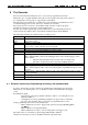
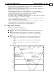
8.4 Programming the length and the resolution
The length and the resolution of the recorded signals is programmed by the RP[0],RL, and
RG command.
RP[0] defines what is the basic time quantum of the recorder.
RP[0]=0 Synchronize the recorder to the speed or position control cycles. The time
quantum of the recorder will be
TS4
RP[0]=1 Synchronize the recorder to the torque cycles. The time quantum of the
recorder will be TS.
RP[0] is set automatically by the UM (Unit mode) command.
The torque mode UM=1 sets RP[0] to 0.
All the other unit modes set RP[0] to 1.
RG defines the sampling rate of the recorder, in terms of the time quantum.