
User's Manual


HARSFEN0602
8.2 Signal mapping
The recorder can record many different signals.
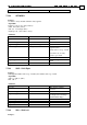
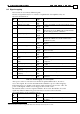
The first 16 signals that may be recorded are compatible with older amplifiers. They are
listed is in the table below.
Signal
ID
Signal Name (Command) Length –
Type
Description
1 Main Speed (VX) Long –
Float
Speed of main feedback sensor in counts/sec
2 Main Position (PX) Long –
Integer
Position accumulation of the main feedback sensor
in counts
3 Position Command (DV[3]) Long –
Integer
Position reference in counts. When external
reference mode is set (RM=1) this signals includes
also the analog reference command.
4 Digital input pins status Short
integer
The IP variable (refer IP in the command reference)
5 Position Error (PE) Long -
Integer
Position tracking error the difference between the
main Position Reference and the main Position
Feedback in counts.
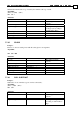
6 Current Command (DV[1]) Short –
Float
The Current reference to the current controller in
amperes.
7 DC Bus Voltage Short –
Integer
Bus voltage in volts.
8 Auxiliary Position (PY) Long –
Integer
Position accumulation of the auxiliary feedback
sensor in counts
9 Auxiliary Speed (VY) Long –
Float
Speed of auxiliary feedback sensor in counts/sec
10 Active current command
(IQ)
Short –
Float
The active part of the vectored current reference in
amperes.
11 Reactive current command
(ID)
Short –
Float
The reactive part of the vectored current reference
in amperes.
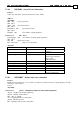
12 Analog Input 1 (AN[1]) Short –
Float
Analog input 1 after offset compensation of AS[1]
in volts.
13 Reserved
14 Motor current phase A
(AN[3])
Short –
Float
Phase A current in amperes.
15 Motor current phase B
(AN[4])
Short –
Float
Phase B current in amperes.
16 Speed Command (DV[2]) Long –
Float
Speed reference to the speed controller in
counts/sec.
Table 8-2: Default mapping of recorded signals
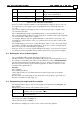
After power-on, the recorder can access the first 16 signals tabulated above. In order to
access other signals, the recorder must make them available in a process called "mapping".
In the mapping process, the ID's of the desired signals is mapped to the recorder "cells". On
power-on, the signals of Table
8-2 are mapped to the recorder "cells"
2
.
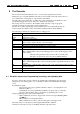
The table below lists some more signals available to the recorder. The full list of recorded
signals may differ for Harmonica grades and releases. It can be retrieved from the
personality partition of the serial flash memory.
Signal
ID
Signal Name (Command) Length –
Type
Description
17 Field angle Short Stator field angle, 1024 counts per electrical
revolution
18 Commutation sensor
Long
–
The position counter, counted modulo a mechanical
2
The word "cell" is used for a logical ID that can be directly referred by the recorder.