
User's Manual


HARSFEN0602
DV[3]
Position
command
-
Speed command
(DV[2], Amp)
Position
Controller
KP[3],GS[9]
FF[2] d/dt
Automatic
Controller
Selector
0
Fixed if
GS[2]=0
Main Position
sensor
Auxiliary Position
Sensor
Position feedback
UM=4
UM=5
CommandPiePos
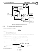
Figure 41 – Block Diagram of The Dual Loop Controller
15.3.2 The Parameters of the Position Controller
The position controller is implemented as a cascaded loop, the inner loop is a speed controller and the outer
loop is a simple gain: The simple gain operates on the position error,
)(te
POS
:
)()()( tkPosFeedbactPosCommandte
POS
−= [counts]
to give [Internal speed units, see “Units” section]
)()( teKtCommandPI
POS
Out
P
⋅= .
However when the position error,
)(te
POS
, is too large the gain is modified to avoid instability,
Out
P
K is
replaced by
))(()))((2)),((min( tesignteabsteabsK
POSPOSPOS
Out
P
⋅⋅⋅⋅ α .
where
]9[2 GS=⋅ α
The above formula assures that the speed controller will not be demanded to decelerate beyond
α count/sec
2
.
GS[9] must be calculated with
α as the 80% of the highest deceleration the motor can produce with the
current of PL[1].
The inner loop is a speed controller, described previously in this chapter.
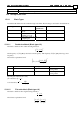
The parameters of the non-scheduled position controller are:
Parameter Description
KP[3]
Proportional gain ,
Out
P
K
GS[2] Controller gain selector
GS[9] Acceleration limit
VL[2],VH[2] Maximum speed command
FF[2] Speed Feed-forward
UM For UM=4 the position feedback is taken from the auxiliary encoder